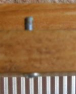
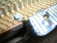
Something like this channel for the heat,
Slight angle and silicone washers.
This also gives me a double skin, taken from the ideas of the exhaust pipes on Japanese motor bikes to stop the blueing on the manifold. They put a double skin inside the pipes and it stopped the chrome going blue. Heat reduction.
The heat should create a chimney effect inside the channel. To be tried!
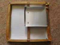
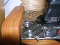
I have put pins through the top that now engage with the front panel, just me being safety conscious.") (nuts recessed into the wood)Its now impossible to remove the top plate without physically breaking it apart unless the two screws are removed from the back.(the top is a slide forward fit).
(nuts recessed into the wood)Its now impossible to remove the top plate without physically breaking it apart unless the two screws are removed from the back.(the top is a slide forward fit).
The fit still looks the same.
Still lots to do.

Regards
M. Gregg
Slight angle and silicone washers.
This also gives me a double skin, taken from the ideas of the exhaust pipes on Japanese motor bikes to stop the blueing on the manifold. They put a double skin inside the pipes and it stopped the chrome going blue. Heat reduction.
The heat should create a chimney effect inside the channel. To be tried!
I have put pins through the top that now engage with the front panel, just me being safety conscious.
(nuts recessed into the wood)Its now impossible to remove the top plate without physically breaking it apart unless the two screws are removed from the back.(the top is a slide forward fit).The fit still looks the same.
Still lots to do.
Regards
M. Gregg
Attachments
Last edited:
OK,
So the new power Tx arrived yesterday so the soldering iron went into overdrive. Why? cuz I'm impatient.
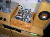
And yes the power supply is not optimised and it hums like crazy, BUT..there must be something about the EF86 driving EL84 in RH84 topology.. Because I have had a few.. and its been on for about 4 hours.
Lashed up for a test. I'm going to have to rethink a few things, the caps next to the EF86's are getting roasted. So a move is on the cards, however I do like the sound. Perhaps its the Ale, the hum is a PITA, but its turned up so I can't hear the hum over the music..
Its raw and ready, quite refreshing don't you know
Everything from LA woman(Doors) to POCO and its Quite good. That hum is going to have to GO though. LOL. Sigh...
After the experience tonight, I will spend some time optimising this unit, It's very good in a raw and ready kind of way!
Shame Alex can't keep himself in check, he seems to have a lot to offer. Not even the knobs fitted....stuff it..LOL
I must admit I have never heard EL84 SE sound quite like this!
Tip of the day, If you use Hammond mains Tx fasten a ty rap about 3cm from the outlet of the Tx then twist/plait from there. The terminations could be a bit more mechanically finished. Anyway it creates a barrier so you don't twist the connections under the Tx insulation.
So still lots to do! As always its getting it right without losing the drive it has now!
Regards
M. Gregg
So the new power Tx arrived yesterday so the soldering iron went into overdrive. Why? cuz I'm impatient
.And yes the power supply is not optimised and it hums like crazy, BUT..there must be something about the EF86 driving EL84 in RH84 topology.. Because I have had a few..
and its been on for about 4 hours.Lashed up for a test. I'm going to have to rethink a few things, the caps next to the EF86's are getting roasted. So a move is on the cards, however I do like the sound. Perhaps its the Ale, the hum is a PITA, but its turned up so I can't hear the hum over the music..
Its raw and ready, quite refreshing don't you know
Everything from LA woman(Doors) to POCO and its Quite good. That hum is going to have to GO though.
LOL. Sigh...After the experience tonight, I will spend some time optimising this unit, It's very good in a raw and ready kind of way!
Shame Alex can't keep himself in check, he seems to have a lot to offer. Not even the knobs fitted..
..stuff it..LOLI must admit I have never heard EL84 SE sound quite like this!
Tip of the day, If you use Hammond mains Tx fasten a ty rap about 3cm from the outlet of the Tx then twist/plait from there. The terminations could be a bit more mechanically finished. Anyway it creates a barrier so you don't twist the connections under the Tx insulation.
So still lots to do! As always its getting it right without losing the drive it has now!
Regards
M. Gregg
Attachments
Last edited:
Just some more,
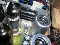
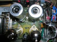
I have moved the caps for the screen supply on the EF86's and added a heat shield to protect the front panel. The caps have been moved quite some distance, the resistor from the B+ supply is still straight on under the board.
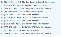
So there is only two kimber film caps under the board the rest is resistors BOM is attached for the RH84 with EF86 driver,
Still more to do, the fuses that are temporary mounted on the OP Tx's for each channel for initial power up (200mA QB) just in case. Will be moved and fuse holders mounted on the back panel.
The control doubler is protected by SS fusing off the heater supply. The 5y3 heater supply is protected by SS 4A fuse mounted from a spare valve base connection to the heater connection, same as the 100 ohm anode resistors.
I used Kimber Kap for the coupling, RRR resistors and Kiwame/takman MF 1W for the feedback. The BOM also contains parts for the Cathode standard fixed bias, however I used the 5V reg and 110 ohm RRR resistor with Muse 220uF bypass and 22Vzener combination. These cathode components are mounted behind the EF86 cans for heat protection and easy bias check.
Still more to do, Its been on test for about 3 hours. You have to test it don't you..
Regards
M. Gregg
I have moved the caps for the screen supply on the EF86's and added a heat shield to protect the front panel. The caps have been moved quite some distance, the resistor from the B+ supply is still straight on under the board.
So there is only two kimber film caps under the board the rest is resistors BOM is attached for the RH84 with EF86 driver,
Still more to do, the fuses that are temporary mounted on the OP Tx's for each channel for initial power up (200mA QB) just in case. Will be moved and fuse holders mounted on the back panel.
The control doubler is protected by SS fusing off the heater supply. The 5y3 heater supply is protected by SS 4A fuse mounted from a spare valve base connection to the heater connection, same as the 100 ohm anode resistors.
I used Kimber Kap for the coupling, RRR resistors and Kiwame/takman MF 1W for the feedback. The BOM also contains parts for the Cathode standard fixed bias, however I used the 5V reg and 110 ohm RRR resistor with Muse 220uF bypass and 22Vzener combination. These cathode components are mounted behind the EF86 cans for heat protection and easy bias check.
Still more to do
, Its been on test for about 3 hours. You have to test it don't you..Regards
M. Gregg
Attachments
Last edited:
Something I would add,
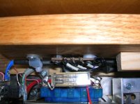
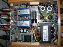
The 260G power Tx seems to have a lot of stray flux. On first power up I had some magnetic coupling with the one channel. This was fixed by lifting the OP Tx and power Tx with cork tile off the chassis.
If I was to build again I would make the chassis slightly larger (not a lot) just enough to keep the OP Tx's further into the right hand corner. Its the price of trying to shrink the size..
NB the base plate is aluminium and lifting the Tx's cured it! You would think it would be a problem with steel..anyway's.
I will use the internal ducting for the Rectifier, however the EL84's are biased very hot in this circuit. So some top venting may be required, I'll have to see its running with the top open at the moment so I can get an idea of the temp and heating of components. I am also glad I mounted the 260G on the cork it runs quite warm and I don't want the small chassis base plate heating up. its working well at the moment! Power Tx and chassis are just warm to the touch.
Regards
M. Gregg
Last edited:
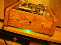
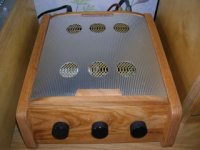
First test in the box,
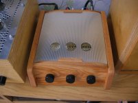
Some extra venting and earth bonding of mesh to top plate and back plate to earth connection.
The weather is quite warm and its just warm to the touch with constant warm air out of the back and top vents.
WAF is high, she walked though and looked and the Ohhh where are the valves?..there inside..
Still a few things to do..
Its playing the Eurythmics greatest hits at the moment...there must be an Angel playing with my heart...Da, Da, da....

Regards
M. Gregg
Some extra venting and earth bonding of mesh to top plate and back plate to earth connection.
The weather is quite warm and its just warm to the touch with constant warm air out of the back and top vents.
WAF is high, she walked though and looked and the Ohhh where are the valves?
..there inside..Still a few things to do..
Its playing the Eurythmics greatest hits at the moment...there must be an Angel playing with my heart...Da, Da, da....
Regards
M. Gregg
Attachments
Last edited:
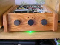
Final instalment,
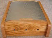
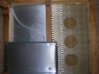
I have made some more vents in the top plate, after 5 hours of playing the top plate started getting hot. I tried it without the top channel for the rectifier thinking the new vents would sort the heat, and it got to hot to touch in about 1 hour, so the channel went back in. Its just warm now and has been on for about 4.5 hours. Again just lashed in for a test!
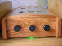
Same layout as for the front mesh and additional bonding.
I could have just used a mesh top plate. However it would show all the internals. As it is now I can just see the tubes glowing if I look at the right angle.
So its Van Halen volume 1 at the moment..
The slide forward top and then push down at the back so there are just 2 screws at the back works well.
I'm not a fan of Hammond mains Tx's I am running it at just over half power and it gets quite warm. The heater winding is drawing about 1.5 A and its rated for 5A, The B+ is rated 200mA and running at 100mA, Rec winding is running at about 2A its rated at 3A. The voltage doubler for the control is working well.
I have kept all electrolytic caps above the board so they can be changed easily/or uprated.
Do I like the sound ...yes.
I guess you already know its the RH84 EF86 driving EL84.
You can just see the LED's not selected in a dark room, they look OFF in the daylight.
Regards
M. Gregg
I have made some more vents in the top plate, after 5 hours of playing the top plate started getting hot. I tried it without the top channel for the rectifier thinking the new vents would sort the heat, and it got to hot to touch in about 1 hour, so the channel went back in. Its just warm now and has been on for about 4.5 hours.
Again just lashed in for a test!Same layout as for the front mesh and additional bonding.
I could have just used a mesh top plate. However it would show all the internals. As it is now I can just see the tubes glowing if I look at the right angle.
So its Van Halen volume 1 at the moment..
The slide forward top and then push down at the back so there are just 2 screws at the back works well.
I'm not a fan of Hammond mains Tx's I am running it at just over half power and it gets quite warm. The heater winding is drawing about 1.5 A and its rated for 5A, The B+ is rated 200mA and running at 100mA, Rec winding is running at about 2A its rated at 3A. The voltage doubler for the control is working well.
I have kept all electrolytic caps above the board so they can be changed easily/or uprated.
Do I like the sound ...yes
.I guess you already know its the RH84 EF86 driving EL84.
You can just see the LED's not selected in a dark room, they look OFF in the daylight.
Regards
M. Gregg
Attachments
Last edited:
I have a few ideas,
I intend to remove the cork under the mains Tx and support it on 4X 6mm nuts or stand offs. To allow the air to get between the Tx and the bottom plate.
The problem with building like this is keeping the bottom and top plate cool.
The flux from the mains Tx can be a problem in such close conditions.
It creates many more problems than the standard chassis method.
Also tube height is an issue. The PYE Mozart is an interesting layout and I would probably try that method next time.
Plan well before your build. Good Luck!
I hope to try the triode RH84 81 driving el84 to see which is better!
Then the Mullard 3-3 time might be an issue..
Regards
M. Gregg
Last edited:
Just an update,
I realised that if I fit the spacers to the mains Tx then that gives me quite a large area to put vent holes directly under the power tx between the base plate and the laminations. OK so why not use a mesh bottom plate, well because I tried this in the past and the holes are never where you want them. They don't line up and if you drill the mesh it breaks into the other holes. Also I like to give strength to areas that need it, and I like to block the holes in the chassis so its not easy to get direct contact with the B+. Think about the holes under the mains Tx with the spacers. behind the holes is the lamination block so the air flow is going to be at 90 Deg no direct access. Ie its hard to just push something in to the chassis. This is just an example because you would have to lift the amp up while its on to get access. The top vent holes, the B+ is covered with the top channel etc.
You can't make it fool proof, however you can try to make difficult. Just trying to build with safety in mind. The other way is using distance from the vent holes. Ie how long has the hair clip etc got to be to reach a supply. Its all good fun.
That's probably why the standard chassis and cage is so good! And another reason to fit discharge resistors. Its not very good if the B+ is up for weeks. That's when little fingers go to work when your not looking!
Might be of interest to someone.
Regards
M. Gregg
Last edited:
Final update..
Mains transformer mounted on 6mm nuts with vent holes under it.
The Mains Tx runs cooler, and it makes quite a difference to bottom plate heat.
Temp fusing for the B+ now removed and permanent fusing before the first cap after the rectifier fitted to back panel.
 ..I can't strip it..
 don't want to. Its playing now
How can I play it if its in bits..Just another manic Monday..
Might have to have a drink later and think about it!
Humm how much would another set of Tx's be
Regards
M. Gregg
Mains transformer mounted on 6mm nuts with vent holes under it.
The Mains Tx runs cooler, and it makes quite a difference to bottom plate heat.
Temp fusing for the B+ now removed and permanent fusing before the first cap after the rectifier fitted to back panel.
..I can't strip it.. don't want to. Its playing now How can I play it if its in bits
..Just another manic Monday..Might have to have a drink later and think about it!
Humm how much would another set of Tx's be
Regards
M. Gregg
Last edited:
Just thought I would add this,
The EL84 cathode cap seems to make a big difference in the RH84. YMMV.
Silmic II made it sound very dark but interesting...strange because I normally like silmic II
Muse ZX seem to be open and is the favourite at the moment. I'm running 220uF 25V.
so much to do...
I would not use Tant caps every tant cap that has failed in the past has caused faults in equipment due to short circuit. This is experience from fault location in the past.
Regards
M. Gregg
The EL84 cathode cap seems to make a big difference in the RH84. YMMV.
Silmic II made it sound very dark but interesting...strange because I normally like silmic II
Muse ZX seem to be open and is the favourite at the moment. I'm running 220uF 25V.
so much to do...I would not use Tant caps every tant cap that has failed in the past has caused faults in equipment due to short circuit. This is experience from fault location in the past.
Regards
M. Gregg
Just an observation,
YMMV, put the bleeder for the RH power supply across C1 only.
(C1 the PSU first cap after the rectifier before the choke.)
Does it make a difference if put on C2, on mine it does. Even very high values of R (600k +). Even if the bleeder is put on C1 and C2 it has an effect.
Might be of interest to someone.
Regards
M. Gregg
Last edited:
Time to rip it to bits and try the other circuits.
Regards
M. Gregg
Amazing craftsmanship - although not particularly classic...
Did you really rip it to bits - or that was just a joke?
Amazing craftsmanship - although not particularly classic...
Did you really rip it to bits - or that was just a joke?
It was a joke..
It sits next to my other amps..and gets used quite a lot..
Regards
M. Gregg
- Status
- This old topic is closed. If you want to reopen this topic, contact a moderator using the "Report Post" button.
- Home
- Amplifiers
- Tubes / Valves
- What do you think..OP Tx