More details please!
"There has been a failure in the attempt to use specifications to
characterize the subtleties of sonic performance. Amplifiers with similar measurements are not equal, and products with higher power, wider bandwidth, and lower distortion do not necessarily sound better. Historically, that amplifier offering the most power, or the lowest IM distortion, or the lowest THD, or the highest slew rate, or the lowest noise, has not become a classic or even been more than a modest success."
From: Single-Ended Class A - Nelson Pass
http://www.passlabs.com/pdf/seclassa.pdf
Could you Email Mr. Pass with the details on the appropriate measurements. He only has about thirty years of amplifier design experience, but could obviously use your advice on how to rectify this dilemma. This is no attempt to speak for him personally, but it sounds like to me that he would be grateful for your help. I feel that I could also benefit from your advice on this highly controversial subject.
Thanks in advance,
Fred
PMM said:got a point,
however i think maybe technology may have had a bit more impact on things electronic and mechanical than on the process involved in throwing paint on a canvas.
Comparing painting and music may be a closer thing.
As I happen to paint myself, and also like to read about the
techical aspects of pigments etc., i would say both yes and no.
Beginners, many experienced amateurs and even some
professionals use studio-quality paint (I have felt the proper
term should be study-quality, since that is what it means)
instead of reliable artist-quality paint, and the same for canvas
etc. That is often a big mistake, as is also pointed out by
experts in artist materials. The cheaper stuff can be much more
difficult to work with. This is especially evident in water-color
(aquarelle or similar in all other languages). I started with
watercolour and, of course, bought cheap paint and paper.
It was extremely difficult to work with, but at first I thought it
was my fault, until I decided to invest in a sheet of good
paper, which made an enormerous difference. Then getting
artist-quality paint makes a lot of difference too, especially
in watercolour.
On the other hand, a good artist (not just a good painter)
can usually still create great paintings with inferior material.
Some have even used ordinary industrial-grade paint etc.
This reminds of jonathan Carrs recent claim, that design
and PCB layout is often more important than the actual
components used (off the top of my head, and not literal).
One important aspect in art, however, which is less important
in electronics is to "design" for an extremely long "product
lifetime". Here the material and the knowledge of how to handle
it makes an enormeous difference. We have examples of
paintings from the Renaissance which are still in very good
condition (far from all though, eg. Leonardo da Vinci who liked
to experiment with new techniques). on the other hand we
Anselm Kiefer, whose works german museums has paid very
large sums for buying up. They now have to invest
enormeaus sums of money to restaurate his paintings, some
of which are barely ten years old. He makes great paintings,
but he obviously dosen't bother much about the well-documented rules for how to build up a painting techniqually. Another example,
I read just a few hours ago about the now obsolete (genuine)
Asphaltum pigment which has been used for some 500 years,
often with serious problems with ageing. Howver, Rembrandt
and other comtemporary dutch painters used it and there is
still no sign of problems, because they knew its limitations and
that there was only one way it could be used safely.
Why do I always write such lengthy posts.


Hugh,
thanks for your response. I had always wondered what happened to Mr Tilbrook, is he still around? I liked his projects cos he provided lots of technical detail which appealed to a person like me (read anal!)
I built the ETI5000 and it served me well through my years of renting houses whilst studying (read partying!), it was a very rugged design i can assure you. Later when it was replaced by the AEM6000 was absolutely amazed at the improvement in sound quality that it gave me. It is the last time I have had the sound quality improvement with a loudspeaker amp!!
I then donated the 5000 to a friend who used it for a few years and it only met its demise when he found a girlfriend who so liked putting potplants on top of electrical devices. the plants were okay it was the overflow of water that got inside that did it.
I completely agree with you about the measurement thing as i am convinced by the results of my projects. My "dull & lifeless" synopsis applies to bot the Class A and the subsequent Ultra LD class AB published by Silicon Chip. Sorry cambe.
Fred D who are you asking for measurement details from, sorry i don't understand.
Fred D who are you asking for measurement details from, sorry i don't understand
The series of post by MikeK left me with the impression that he might follow up with more detail. Perhaps he was a bit pressed for time, but the observations make some claims that many might dispute. As these threads go, they usually greatly expand in detail and discourse before closing.
From mikek;
"A three gain-stage design. The final gain stage is notorious for quiescent current instability.
Outside of a configuration with gain in the output stage, i cannot conceive of any circumstances in which three gain stages are necessary, or required."
"if the published distortion figures are good and it doesn't 'sound' right, then it's not being measured right..."
And in his response to:
........one of the designers aims was to get lowest THD, remember it was 86 and that was everything back then.
"...it still is everything really, or should be......."
These post left me with the impression that he might follow up with more detail on very brief but seemingly quite strongly held opinions. They would seem to be intended to provoke further discussion. Perhaps he was a bit pressed for time, but the observations make some claims that many might dispute and can't be his last word on this topics so lightly touched on.
I am puzzled by the stated goal of low distortion while rejecting three stages of voltage gain as unnecessary. The higher open loop gain would generally result in lower measured distortion due to the increase in loop feedback. Rejection of a topology that would likely result in lower distortion, seems in direct conflict with the last two statements. Surly there is more to come to clarify this paradox.......
Even more puzzling is the rejection of this topology after advocating the Marantz PM-17 (proof of concept implies approval I think) which has three voltage gain stages and a triple emitter follower, an output stage with no voltage gain! This would appear to be at least a first cousin to the rejected topology refered to in the first post.
http://www.diyaudio.com/forums/showthread.php?postid=192255#post192255
Am I the only one confused by these seemingly contradictory post ?
Hey Dr Gene Scott,
I missed your earlier post. i am new to this game, my first post here, and I keep finding posts that i missed earlier. Must try to figure it out.
Anyway i will zip the file and send to you when I am home later
(spent a lot of time today goofing off at work over this post , problem with being on the other side of the world)
still kind of interested to hear if anyone knows of a circuit that will give better sonic performance (I know it is a difficult/kinda stupid question that raises lots of subjective and opinionated issues but I gotta ask)
I missed your earlier post. i am new to this game, my first post here, and I keep finding posts that i missed earlier. Must try to figure it out.
Anyway i will zip the file and send to you when I am home later
(spent a lot of time today goofing off at work over this post
, problem with being on the other side of the world)still kind of interested to hear if anyone knows of a circuit that will give better sonic performance (I know it is a difficult/kinda stupid question that raises lots of subjective and opinionated issues but I gotta ask)
mikek said:
if the published distortion figures are good and it doesn't 'sound' right, then it's not being measured right...
mikek,
oh no. We still have much to learn what to measure and how to find correlation between measurements and sonic results. THD, IMD and other quasi-stationary measurements do not provide enough information. Dynamic spectral distortions of the complete sound chain should be examined. And a designer must listen and listen, to compare, to compare with live non-electronic and non-amplified music.
PMA said:
....THD, IMD and other quasi-stationary measurements do not provide enough information.......
.........this is the single most indefatigable myths in engineering......i hold out no hope whatever that it will disappear anytime soon.......mountains of evidence not withstanding.....
mikek,
have you ever listened to the 2 amps having the same THD and IMD specs. Did they always sound same. I have done it for more than 25 years. THD and IMD are not enough to specify sonic difference. It is pretty more complex and that is why it is interesting and that is why we still try to find better solutions.
have you ever listened to the 2 amps having the same THD and IMD specs. Did they always sound same. I have done it for more than 25 years. THD and IMD are not enough to specify sonic difference. It is pretty more complex and that is why it is interesting and that is why we still try to find better solutions.
More puzzling evidence
"A three gain-stage design. The final gain stage is notorious for quiescent current instability.
Outside of a configuration with gain in the output stage, i cannot conceive of any circumstances in which three gain stages are necessary, or required."
In post # 118 of Output stages with gain Enhance Slew rate
http://www.diyaudio.com/forums/showthread.php?postid=191570#post191570
You offer up the design below.
The op amp is usually at least 2 voltage gain stages. The conversion of the op amp output current to a voltage by Q1 and Q2 which is a voltage gain stage with the voltage across R8 as the input single. Whether this is a voltage gain stage greater than depends on the ratio between R8 and R4, R6. The contributions of additional poles and distortion from the op amp output stage driving R8 as well as the contributions of Q1 and Q2 would still be similar to a typical voltage gain stage even in the case of an output voltage gain less than unity. One could certainly not pass it off as a follower even in that case. The distortion contribution from the op amp follower op amp stage are well know and the use of in loop buffers becoming very common to minimize this problem.
So now we are left with an amplifier with a least FOUR voltage gain stages and an emitter follower output stage with no voltage gain. Doesn't this conflict sharply with the statement about three gain stages made in this thread in criticism of the initial design under scrutiny? In the US we have an old routine of asking the victim of a blow to the head "How many fingers am I holding up?" to access his mental state and the medical severity of the impact to there brain. Along the same line of concern may I ask, "How many gain stages am I holding up?"
Thanks for your attention in this matter,
Fred
Attachments
Re: More puzzling evidence
In view of the brevity of my observations made earlier in the thread, Nelson's objections may, prima facie, appear valid. However, any reservations held in this regard will now be shown to be illusory.
'Higher open loop gain' is of itself entirely meaningless, unless and untill we define with precision at what frequency and/or bandwidth this worthy quantity is being sustained.
This is because, in the interest of stability, a 'higher' open loop gain, (presumably at DC), cannot be sustained indefinitely.
In other words, the higher the open loop gain, the heavier the compensation required for the same stability margins.......you are then proverbialy back to square one.
Of greater relevance, is the quantity of open-loop gain at a defined frequency, (say 20KHz), that can be safely accommodated without compromising the systems stability.
In broad terms, using three gain stages with a view to generating higher open loop gain, and therefore lower distortion is fallacious, precisely because the extra gain comes at the expense of additional poles contributed by the extra gain stage, which now have to be compensated for........taking you nicely back to square one!!
In other words, your compensation will have to be more rigorous, probably resulting in less loop gain at 20KHz than you otherwise might have with a two gain stage design......ergo more distortion at HF than the usuall two stage approach...the mother of all electronic ironies n'est pas?!!
Again you'll find there is no contradiction whatever........
......carefull study of the thread to which you give reference , and my statement in this thread in this regard should have by now clarified matters.
http://www.diyaudio.com/forums/showthread.php?postid=192255#post192255
The purpose of the slew enhancement thread was to demonstrate one simple mechanism by which such may be attained......as i emphasised in that thread, i did not find excessively high slew rates neccesary......the design examples at the end of the thread were merely posted to demonstrate proof of concept...
...ergo, that the generation of gain in the output stage, ( if desired.....for the porpose of enhancing said slew!!) is better achieved by using a complementary Wilson mirror, whose parasitic collector capacitances are bootstrapped, (thereby minimising there contribution to the foward path transfer function of the system).
It should also be noted that one advantage of such a scheme is that, although more stages are encapsulated by the global feedback loop, the input stage can consist of high Ft transistors which typically, come in low Vce(max). non- dominant poles can therefore be further relegated beyond the systems Ft.
I think it is now self evident that i did not as you say, 'advocate' the pm-17 per se, and that this was merely held up as an example of a design thta proves the viabilty of the concept disdained by yourself and mr. J homo.
Fred Dieckmann said:
I am puzzled by the stated goal of low distortion while rejecting three stages of voltage gain as unnecessary. The higher open loop gain would generally result in lower measured distortion due to the increase in loop feedback. Rejection of a topology that would likely result in lower distortion, seems in direct conflict with the last two statements. Surly there is more to come to clarify this paradox.......
In view of the brevity of my observations made earlier in the thread, Nelson's objections may, prima facie, appear valid. However, any reservations held in this regard will now be shown to be illusory.
'Higher open loop gain' is of itself entirely meaningless, unless and untill we define with precision at what frequency and/or bandwidth this worthy quantity is being sustained.
This is because, in the interest of stability, a 'higher' open loop gain, (presumably at DC), cannot be sustained indefinitely.
In other words, the higher the open loop gain, the heavier the compensation required for the same stability margins.......you are then proverbialy back to square one.
Of greater relevance, is the quantity of open-loop gain at a defined frequency, (say 20KHz), that can be safely accommodated without compromising the systems stability.
In broad terms, using three gain stages with a view to generating higher open loop gain, and therefore lower distortion is fallacious, precisely because the extra gain comes at the expense of additional poles contributed by the extra gain stage, which now have to be compensated for........taking you nicely back to square one!!
In other words, your compensation will have to be more rigorous, probably resulting in less loop gain at 20KHz than you otherwise might have with a two gain stage design......ergo more distortion at HF than the usuall two stage approach...the mother of all electronic ironies n'est pas?!!
Fred Dieckmann said:
Even more puzzling is the rejection of this topology after advocating the Marantz PM-17 (proof of concept implies approval I think) which has three voltage gain stages and a triple emitter follower, an output stage with no voltage gain! This would appear to be at least a first cousin to the rejected topology refered to in the first post.
http://www.diyaudio.com/forums/showthread.php?postid=192255#post192255
Am I the only one confused by these seemingly contradictory post ?
Again you'll find there is no contradiction whatever........
......carefull study of the thread to which you give reference , and my statement in this thread in this regard should have by now clarified matters.
http://www.diyaudio.com/forums/showthread.php?postid=192255#post192255
The purpose of the slew enhancement thread was to demonstrate one simple mechanism by which such may be attained......as i emphasised in that thread, i did not find excessively high slew rates neccesary......the design examples at the end of the thread were merely posted to demonstrate proof of concept...
...ergo, that the generation of gain in the output stage, ( if desired.....for the porpose of enhancing said slew!!) is better achieved by using a complementary Wilson mirror, whose parasitic collector capacitances are bootstrapped, (thereby minimising there contribution to the foward path transfer function of the system).
It should also be noted that one advantage of such a scheme is that, although more stages are encapsulated by the global feedback loop, the input stage can consist of high Ft transistors which typically, come in low Vce(max). non- dominant poles can therefore be further relegated beyond the systems Ft.
I think it is now self evident that i did not as you say, 'advocate' the pm-17 per se, and that this was merely held up as an example of a design thta proves the viabilty of the concept disdained by yourself and mr. J homo.
PMA said:
mikek,
oh no. We still have much to learn what to measure and how to find correlation between measurements and sonic results. THD, IMD and other quasi-stationary measurements do not provide enough information. Dynamic spectral distortions of the complete sound chain should be examined. And a designer must listen and listen, to compare, to compare with live non-electronic and non-amplified music.
i would respectfully reiterate that if the published distortion figures are good and it doesn't 'sound' right, then it's not being measured right...
An obvious example of this is the THD into 8 ohm test, which really tells you next to nothing about the real life load driving capabilities of two competently designed units, (in terms of topology and circuit layout), if one of the units uses a marginaly specified power supply.
The most significant difference between amps. of differing provenance, is the quality and robustness of the power supply, and the ability of the amp. to effortlessely deliver the current required to maintain its rated voltage swing into virtually any transducer you may care to use, at low THD
Re: Fred D who are you asking for measurement details from, sorry i don't understand
To continue NP=FD(?),
....that is not to say that a triple gain-stage amp., as shown at the beginning of this thread, cannot be improved upon by employing unusual compensation.
Nested miller compensation is an obvious example, probably supplemented by feedfoward compensation, to by-pass one of the gain stage at HF.....but this would intoduce pole-zero doublets
before the systems transition freq., making for profoundly mediocre settling time...etc..etc...
incidentally, this is probably why no figures for settling time are given for the lm118....
The following is i've found, a usefull precursor to comprehending nested compensation...
http://patimg1.uspto.gov/.piw?Docid...ageNum=&Rtype=&SectionNum=&idkey=B17B52FDAF72
....tiff viewer required....
Nevertheless, i am satisfied there is no pressing need for a three gain-stage design for the sole purpose of reducing distortion in linear audio power amps.
The defense rests.
I give up
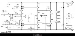
Can't believe how long I have spent on this. I can't get a better quality image that will post, If I get the image down to 100k it is still bigger than the 800x1200 format (can't work that one out), zipping doesn't do much at all. If anyone wants a better quality jpeg or tif or GIF or pdf email me & I will send from work in the next day or two (I only have dialup at home).
A couple of points re my amp compared to the schematic.
I run 3 pairs of mosfets on the output. The reason for this is when i was starting construction i got my old Nakamichi tapedeck (remember those?) serviced and got talking to the techie who said mosfet output stages are great but you need to parallel lots to lower the output impedance. so I thought this guy knows lots more than me (not terribly difficult I admit) so lets put an extra set of mosfets in there. In the text for the amp project Tilbrook talked about adjusting the value of R19 & 20 for users who wished to use different numbers of output devices, 150R, 220R & 270R. 220R was for 2 sets as schematic, the 150R shown in the schematic was actuallyan error listed in accompanying errata. I assumed 150R to be correct for 3 sets of output devices.
The Silicon Chip Ultra LD amp that so dissapointed me did have a positive outcome of sorts. That design uses a seperate regulated supply for input & VAS and the I thought they produced a nice tidy circuit capable of handling decent rail voltages for which PCB's are available. It was altogether to tempting for a tinkerer like me so I made a couple and tweaked the values of parts to produce arail voltage about 2.5v (a researched guess, any comments) higher than the 75 required by the output stage, hacked the PCBs of the amps to seperate the supplies and to my constant amazement nothing blew-up or failed to perform.
The improvement was significant though I have to admit i also replaced all 'lytics on the amp boards with panasonic FC's and bypassed the decouplers with MKP's (more tinkering) at the same time so what did what is a mystery.
Funny thing also i run max bias and the heatsink temp dropped a little after this mod (someone going to tell me it was oscillating(break my heart!))
mikek,
of course I do agree that low THD and IMD is a must. I just only wanted to show that these measured mostly into pure resistive load are not enough. I know that you work on amp protection and SOA and that you aware of it.
THD/IMD measured into a resistor must be low, but does not tell much about THD/IMD measured into dummy speaker load or into real speaker with crossover.
PSU circuit is important, but not the only one item responsible for different amp sound. We should probably start different thread")
Pavel
of course I do agree that low THD and IMD is a must. I just only wanted to show that these measured mostly into pure resistive load are not enough. I know that you work on amp protection and SOA and that you aware of it.
THD/IMD measured into a resistor must be low, but does not tell much about THD/IMD measured into dummy speaker load or into real speaker with crossover.
PSU circuit is important, but not the only one item responsible for different amp sound. We should probably start different thread
Pavel
more oil into the fire - Cheever thesis
Have you seen this study
http://w3.mit.edu/cheever/www/cheever_thesis.pdf
I found it to be very interesting reading material......
If you haven't seen it then trust me and read it. Even if yo´u disagree at least it provides another angle to view the measurements and for sure will create feedback....
Ergo
audioasylum responses to this thesis
http://www.audioasylum.com/forums/prophead/messages/2816.html
Ergo
http://www.audioasylum.com/forums/prophead/messages/2816.html
Ergo
Re: more oil into the fire - Cheever thesis
...i have had the opportunity to examine cheever's thesis, (thanks Ergo), and i fear the initial assumptions made, and references cited to justify the work are fatally flawed.
He gives prominence to a subjective review of the cary amp. in 'stereophile', whose lack of intellectual rigor and consistency is legend....for instance, the cary amp.'s lack of global feedback is given fulsome credit for the amps. performance, but we need only recall the Halcro dubbed the best amp. in the world by the same periodical, uses a hefty feedback factor.
Mr. Cheever cites Matti Otala's work on TIM, but sadly appears to
not to be cognisant of the fact that TIM, SID have been demonstrated to be a red herring of the Monster variety.....see P. Baxandal series in wireless world 1978-1979, whose name is conspicuously missing from this thesis....
...considering that the author subsequently cites Dr. Cabot of Audio Precision, i find it inexplicable that he failed to mention an extremely important AES paper by the good Doctor: 'Comparison of non-linear distortion measurement methods' ,(surely an oxymoron? )
http://audioprecision.com/publicati...ent_Methods.pdf
I have difficulty in accepting that this ommision was accidental, as many figures in this thesis are infact directly copied from other publications on the audio precision website.....
ergo said:Have you seen this study
http://w3.mit.edu/cheever/www/cheever_thesis.pdf
I found it to be very interesting reading material......
If you haven't seen it then trust me and read it. Even if yo´u disagree at least it provides another angle to view the measurements and for sure will create feedback....
Ergo
...i have had the opportunity to examine cheever's thesis, (thanks Ergo), and i fear the initial assumptions made, and references cited to justify the work are fatally flawed.
He gives prominence to a subjective review of the cary amp. in 'stereophile', whose lack of intellectual rigor and consistency is legend....for instance, the cary amp.'s lack of global feedback is given fulsome credit for the amps. performance, but we need only recall the Halcro dubbed the best amp. in the world by the same periodical, uses a hefty feedback factor.
Mr. Cheever cites Matti Otala's work on TIM, but sadly appears to
not to be cognisant of the fact that TIM, SID have been demonstrated to be a red herring of the Monster variety.....see P. Baxandal series in wireless world 1978-1979, whose name is conspicuously missing from this thesis....
...considering that the author subsequently cites Dr. Cabot of Audio Precision, i find it inexplicable that he failed to mention an extremely important AES paper by the good Doctor: 'Comparison of non-linear distortion measurement methods' ,(surely an oxymoron? )
http://audioprecision.com/publicati...ent_Methods.pdf
I have difficulty in accepting that this ommision was accidental, as many figures in this thesis are infact directly copied from other publications on the audio precision website.....
- Status
- This old topic is closed. If you want to reopen this topic, contact a moderator using the "Report Post" button.
- Home
- Amplifiers
- Solid State
- what do you think of this schematic?