tubelab.com said:My latest amp... There are several switches (including the ones mentioned above) on this amp that make some changes (like tube or SS rectifier) and some that do nothing. The users will be asked to try each switch and rate what it does to the sound, and find the combination that they like best, in their home with their speakers, and their music.
Briliant idea about the switches that do nothing, I am looking forward to the results!
Regarding MOSFETs and nonlinear capacitances:
Cgd is indeed not a constant but it is not extremely nonlinear as long as you don't go into low Vgd conditions - how low, depends on the actual MOSFET but usually most of the problems are avoided by having a minimum Vgd of about 5-10V. In general, the nonlinearity is higher on lower max Vds rated MOSFETs.
As long as low Vgd is avoided, look for the lowest Cgd (reverse transfer capacitance).
For truly low capacitance, a self-cascoded follower can be used. In this design, there is another MOSFET 'on top' of the follower one, and it's gate is referenced to Vgd_minimum + Ggs_threshold over the output of the follower (This usually ends up being about 10-15V minimum). It is fairly easy to do with a high resistance divider from follower output to +V, with the resistor from follower output to cascode MOSFET (the top one) gate bypassed by a good low inductance capacitor. Relevant protection diodes and gate stopper resistors must be applied of course! This arrangement reduces the apparent Cgd of the follower MOSFET about as much as it's apparent Cgs is reduced due to follower operation - in essence, the top MOSFET bootstraps the Cgd of the bottom one, and the bottom MOSFET drives the Cgd of the top one, for which it has plenty of current available.
It is possible to do this with a BJT-MOSFET combo (BJT for bottom, MOSFET for top device) but not truly suitable for A2 operation as the BJT will suddenly require current from the tube driver stage when grid current of the output stage becomes positive. Even though this load is reduced by Beta of the BJT, it is a much more abrupt change than what you get on MOSFETs, even though the input capacitance of such a combo can be made truly miniscule.
Finally, the Cgs of a MOSFET in a follower conenction is usually reduced proportional to it's Gm. For a given MOSFET architecture, Cgs is roughly proportional with Gm, which is again proportional to it's current handling (think of an incerase in Cgs, Gm, Idmax as paralleling MOSFETs). Unfortunately, so is Cgd - which is why, when chosing MOSFETs for follower applications, it is necessary to use the one with the lowest current handling that satisfies your needs (plus safety factor, of course), as this will give you the lowest Cgd.
mosfet power supplies: +-150V is not enought, it should be +150 -300 or more
That is what I used in my amp. +150 and -300 volts. Easy voltages to make from a 120 volt transformer secondary, which is verry common here.
However, I don't understand a thing.
I guess I wasn't clear when talking about the 845. I was trying to say that an increase in plate voltage requires an increase in bias voltage which allows an increase in drive, resulting in more power for almost any given tube. Just cranking up the plate voltage with no other changes only results in a hotter tube.
Briliant idea about the switches that do nothing, I am looking forward to the results!
The "do nothing" switches are to rate the effectiveness of the tester. I have loaned my amps to a lot of people. That is where many of my sales come from. Sometimes a user will hook up the amp and play with it, but not really pay attention to what he is doing, then they will fill out the review sheet without thinking about it. Other times a person will borrow an amp and never even hook it up. Then they will tell you that it worked great. The "do nothing" switches, along with knowledge about what the other switches do, will allow me to find these users.
Cgd is indeed not a constant but it is not extremely nonlinear as long as you don't go into low Vgd conditions
Unfortunately, all of the experts that I consulted work on GHz frequency logic and RF chips that work at 1.2 and 2.5 volts. A far cry from the hundreds of volts that we play with. That is why I simply ordered a few of every cheap fet that DigiKey sells that can take 600 volts or more and tested them. I tried to pick the lowest current fets that had the lowest capacitances associated with them. Several new parts have appeared since I ran that test, maybe its time to do it again.
tubelab.com said:I use 1100 volts B+. The OPT is 10K ohms. I set the current at 70 ma when using vintage tubes to be safe. I have run the new production Chinese (Shuguang) tubes as high at 110 Ma (over the dissipation limit) with out any issues, although I usually run 80 to 90 mA. There is some sag in the power supply as the current is increased, and some voltage drop in the OPT so the tube sees about 1025 to 1050 volts.
This is what I've been looking for. However, you say that Zl= 10K. The Lundahl iron I've been considering was obviously wound for the Q-Point specified in the 845 spec sheet: Zl= 9.0K. What's the output xfmr you're referring to? That Lundahl iron looks pretty good, but price-wise:

Here is a very preliminary design. This includes little more than basic topology.
Attachments
The transformers that I used were purchased off of Ebay from Handwound Transformers. When he first started selling transformers he actually delivered product and the early ones worked pretty good. I got the pair for $120 including shipping. It only took 4 months to get them.
I got a pair of P-P transformers later on and they don't sound very good. After that he just took peoples money and sent them NOTHING! There are a few threads regarding Mr. Lucas, and it looks like I was one of the few people who actually got working transformers from him.
For a new design it looks like tha Hammond 1638SEA (10 K ohm) about $140 each or the Hammond 1629SEA (6.5 K ohm) at $99 each. If you find anything cheaper let us know.
I am still looking for an OPT for the "big one", an 833A SE amp. I have everything except the OPT. The Hammond 1642SE would work, but it is $260 each and no one has any in stock.
For a power supply consider a voltage doubler fed by a 480 volt "industrial control transformer". Maximum power for minimum money. I got a 750 VA transformer for $22 on Ebay.
tubelab.com said:The transformers that I used were purchased off of Ebay from Handwound Transformers.
Say no more. I caught that thread too.
For a new design it looks like tha Hammond 1638SEA (10 K ohm) about $140 each or the Hammond 1629SEA (6.5 K ohm) at $99 each. If you find anything cheaper let us know.
Anything cheaper, nope, can't help there.

For a power supply consider a voltage doubler fed by a 480 volt "industrial control transformer". Maximum power for minimum money. I got a 750 VA transformer for $22 on Ebay.
Yuppers, considered that:
ICT --> X2 --> active regulator
Gives enough margin for the regulator to hit 1.1KV without dropout. Cheap enough to give each monoblock its own HV PS, and avoid cabling 1100V between a remote PS and the amp.
Hello Giaime,
please consider to use the Gomes Totem pole with 12AX7, it has a gain of 70 and output impedance of 500 ohm; the V+ is about 480V .
In origin this was used to drive a plate of 211 push pull (double Tomem driven from a input unbal/bal. trasf.).
PLEASE leave the FET; it is a non sense with georgeus 211 (in my opinion).
Ciao
Walter Gentilucci
")
In every case is not raccomanded to drive in A2 the grid of big power triodes.
With the Gomes circuit you can have a simply but very efficently way to drive the grid of 211.
With 1250 Vdc and -80 v of bias you have about 60 mA of current, with a load of 10k you will reach about 19w (of course if you use a good 211 not a chinese!). The dissipation of ther tube is about 75w. If you stay within this spec, the Gomes circuit works fine.
The main problem is not the grid current (you don't need!) but the quality of output trasf. It MUST be at the highest level otherwise you can design the best circuit in the world since the Roman empire but the sonic results (mainly in the low frequencies) wil be poor. This means that it is expensive; I worked on some of different circuit and the problem is always the same.
Ciao
Walter Gentilucci
Giaime said:Why this bashing of A2 operation? What kind of problems?
I've heard rumours that grid circuit nonlinearities can compromise sonic quality. I suppose that can happen if your driver has too high Zo. Sounds like a good interstage xfmr or a MOSFET source follower will fix it. I like to use strong drivers that can charge up the input/stray capacitance and improve clipping behaviour on transients anyway.
Other than that, it's an audiophile rumour. Who knows?
Hi Giaime,
Maybe just unfounded fear of asymmetrical driver loading/operation when crossing the border to grid current. Nothing to worry about if done right.
I have auditioned two or three well engineered A2 op amps during the last years (but sadly all of them using the 813 tetrode) and I had not much to object.
Tom
Giaime said:Why this bashing of A2 operation? What kind of problems?
Maybe just unfounded fear of asymmetrical driver loading/operation when crossing the border to grid current. Nothing to worry about if done right.
I have auditioned two or three well engineered A2 op amps during the last years (but sadly all of them using the 813 tetrode) and I had not much to object.
Tom
Why this bashing of A2 operation? What kind of problems?
Maybe this person never built (or heard) a GOOD A2 amp. I realize that it is real easy to build a bad A2 amp. And to build a good one you need an expensive IT transformer, or a FET. Most cathode followers will be asymetrical, and sound bad. Many poorly designed A2 amplifiers do not sound good. Some tubes like the 811A REQUIRE A2 operation unless operated at very high plate voltages. There have been several nice sounding 811A amplifiers built.
about 19w (of course if you use a good 211 not a chinese!).
Yes about 19 watts is what you get from a 211 in A1. It is relatively easy to get 30 watts or more in A2 without violating the specs. If you don't turn up the volume, you never enter A2, but you have more headroom for transients. You can have clipped transients, or loud ones that MAY have some A2 coloration on them.
And by the way I have seen over 40 watts at 5% distortion using Chinese 211's. I certainly am not going to test NOS ones (I only have 2) at this power level.
Those are just my opinions. I have built several A2 amps. All of my DHT designs have A2 capability. It is useful on many tubes (including Chinese 300B's). Even if the tube goes non linear in the grid current region the resulting distortion is less objectional than clipping.
I must say I've made some experiments about Powerdrive, and in general low-Z drive for the output tubes.
I'm driving EL36 push pull in triode mode with a 5687 cathode follower, now it's AC coupled and I can strongly tell the difference in comparison with a differential amp made up with 12AT7. Less gain (obvious) but much more live sound, drums are less compressed.
Now I will try DC couple the cathode follower to the power tube's grid. I'm also doubtful, shall I use a mosfet instead of the cathode follower?
You have heard opinions on both sides. I don't know your particular circuit, but it may be possible to use either. If your circuit permits, try it both ways and let us know which you like best. The cathode (source) resistor can be much lower with a fet, due to its lower on resistance.
I did this a few years ago, and you already know which choice I made. It is also possible to put a pentode into the same circuit. Some say that a pentode makes a better cathode follower. I tried a 12BY7, but wasn't impressed. Perhaps a larger tube would have worked better.
I did this a few years ago, and you already know which choice I made. It is also possible to put a pentode into the same circuit. Some say that a pentode makes a better cathode follower. I tried a 12BY7, but wasn't impressed. Perhaps a larger tube would have worked better.
I'll let you know. For now I've got to build up a stiffer B- supply: because for DC coupling of the driver to the output tubes it has to "sink" driver current other than providing negative bias to the output tubes.
What's the best way? I need about -100/120V. Half wave rectify the HV secondary or better use a transformer with a dedicated winding?
What's the best way? I need about -100/120V. Half wave rectify the HV secondary or better use a transformer with a dedicated winding?
Regarding 211 is interesting to verify that the datasheet from RCA speaks, about class A operations, only for A1 (this means not grid current flows) and the max anode wattage is 75 and 1250 volts max for anode.
Is also explained other class operations, but is not for our purpose (class B and C). In every case the A2 condition is not mentioned.
I can agree if you go on A2 you can have more power but, in sinlge end, the main problem is (again) the transformer followed by the trouble to set the driver stage. Is difficult to understand that, in s.e., the problem is not (only) the final power we can obtain but the capability to drive the load at low frequencies (=give current to a real load ).
The problems at low frequencies are very important, a trasformer with 10 k primary, 4/8 ohm secondary, that is capable to handle about 75 bias (at 1250 Vdc max) and goes down, without problems, to 20 Hz, full power 0 dB, its dimension are equivalent to a main trasf. more than 300w.
I used a power trasf. for High voltage with a double C nucleus capable of 550w at 50 Hz, the dimensions are 13 x 13 cm, heght of 16 cm (enclosed). With the same nucleus on output trasf. (always 10 K) I reach the 20 w at 20 Hz, low THd, good square wave response ( very important to look, you can understand lots of things)) and a good response at high frequencies, the weight was about 9 kg ( about 8 for power). The cost are very high ( about 1200$/pair for output and 400$ for power) and are custom made.
After these experiences, also with 811A and 572 , I switch to a p-p of 300B with dedicated trasf., always double C, custom made, they sound much better , with a driver circuit very simple to set .
These are my opinions, they comes from a long experience on this field.
Happy to dicuss again.
Ciao
Walter Gentilucci
I agree that for any tube amplifier, especially a SE amplifier, that the single most important component is the output transformer. In my case I got the OPT's from a person that took a lot of peoples money and gave them NOTHING. The fact that I got anything from him is unusual, the fact that they are good transformers is really unusual. These transformers weigh over 10Kg each. I ran a frequency response test at 10 watts and got 22 Hz to 33KHz. I am sure that they are not capable of full power at 20Hz but the entire amplifier was built for about $400USD.
I got the transformers first, then started to design the best amplifier that I could around them that fit my budget. I do that with a lot of my designs. I started out to build the "Poor Man's Ongaku" form an article in an old Sound Practices magazine. I was not impressed with the sound that I got from my version of that circuit, so I started changing things. The amp that is on my 845SE web page is the result. It bears no resemblance to the original Ongaku design. I also wanted to use 845's (which can be operated in A2) and 838's (which MUST be operated in A2) because I had some NOS tubes.
True the 211 is not specified for A2 operation. A2 was not common in the 1930's when the original data sheet was written. The RCA data sheet that I have (dated 1936) does list class B modulator service with a plate dissipation of 100 watts. In later books 100 watts was listed for all classes of operation. The data listed for class B operation (1250 plate voltage case) shows a bias voltage of -100 volts, but a peak AF drive voltage of 205 volts (1/2 of 410) this is 105 volts positive on the grid. It also shows a drive POWER of 4 watts (1/2 of 8) dissipated in the GRID. Even in 1936 they were driving the grid positive. Look at the plate curves, they only go to - 125 volts, but show positive values to +225 volts. Plot a load line for a reasonable load (5 to 10 K) and you will see that the curves remain linear well into the positive grid region.
I am not stating that everyone should consider A2 operation. It does require careful design. I am saying that it should not be automatically discounted because it is difficult and uncommon. This started as an exercise in "theoretical" design. It is good engineering practice to consider all possible design solutions, then narrow down the choices based on the given constraints. The common constraints are budget, size, power dissipation, etc. We have all presented our opinions, but it is up to the designer to choose his particular design path.
I built this 845SE amplifier, I also built a push - pull 300B amplifier, and several other smaller SE amplifiers. They are all placed in a rack so that I can use any one of them. The 845SE does not get used as much as the others due to the amount of heat it generates. In the summer here the outside temperature reaches 36 degrees C most days. Even with air conditioning I can run that amp for about 1 hour before it gets too hot in here. It is also quite large. I usually listen to one of the small SE amps. When I want to get loud I will turn on the 300B P-P or the 845SE depending upon my music choices.
This his only a discussion regarding different approach; of course the final goal is the quality of the sound (not only on lab).
I am still working on OPT to reach the best.
In my last design, p-p of 300B, I used a custom opt, as told before, in double C core (as power and choke).
I worked on low output impedance.
I have a switch on output to insert NO feedback, 6 dB of FB and 12 dB of FB.
Without FB the output imp. is less than 2 ohm, with 6 dB is about 0,8 ohm and with 12 dB is 0,45 ohm. This means that, at 10 v - 8ohm out, 1 KHz, if I switch to 4 ohm (with 12 dB FB), I have 9,8 volts. At 20 Hz it goes at 9,1 volts. Great performances because I can drive an hard loudpeaker without problems; in this period one amp is driving a B&W 801 II series. In this case if I switch on NO FB the sound is not clear, on bass, as with 12 FB inserted, this because a large woofer (30 cm diam. , very heavy ) need to be "controlled" by good Damping factor (otherwise you got gummy bass); on other situation with a two way Altec loud speaker (woofer 515B in bass reflex and horn 311-60 with 288H driver), 116 dB and the sound is superb without FB.
On this link:
http://www.multitask.it/FB/A-100Hz-ingusc.jpg
you can find a picture where in blu is the input and red the output
of a 100 Hz square wave, 6 Vp-p on 8 ohm, with 12 db FB.
The response at full power is 0db at 20 Hz, -3dB at 90KHz with no FB; 0dB at 15 Hz -3dB at 120 KHz at 6dB of FB; 0 dB at 12 Hz, -3dB at 230 KHz.
In my opinion is difficult to obtain the same performances with s.e. ( in general).
Ciao
Walter Gentilucci
PowerDrive
Hi TubeLab,
I read your Powerdrive design with great interests. I want to build a single-ended power amplifier using 805. I want to use your Powerdrive to drive the 805 to A2. Will it be feasible and sounding good? If yes, when will your Powerdrive be available for sale?
I want to try the IXYS 10M45 CCS chips that you recommend for plate load on these forums and I will buy some from the Digikey. Can the chips be used to replace the cathode resistor of a self-biased cathode follower (e.g. 6EM7) easily? If yes, can you elaborate?
Thanks.
Regards,
T.C. MA
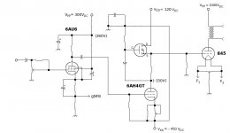
tubelab.com said:Been here built that! Look at the 845SE on my web page.
http://www.tubelab.com/845SE.htm
Look at the second schematic on that page.
I started out building an Ongaku clone, and after several itterations wound up with the amp that you see on that page. The power supply makes a BIG difference in the sound. I have done two power supply designs, and I am still not happy with it. I have a power supply from an old Motorola police radio base station that puts out 1500 volts at 1/2 AMP! It gives the best sound, but weighs 120 pounds and the transformer buzzes loudly.
I use mofet drive. I wanted to be able to drive 211's and 845's interchangeably which requires at least 200 volts peak to peak! I have since used this circuit to drive an 833A, which can draw grid current of over 100mA. You can't get this from a single stage. Even if you could, I don't think that an ECC83 has the slew rate capabilities to swing near this much voltage at say 50 KHz. For that you need current. I think you might get there with the 12AT7 at about 10 mA (or both sides in parallel at 20mA). I have been using them (CCS loaded) in my latest amps because 5842's have become scarce and expensive.
I have called the CCS, mosfet drive combination PowerDrive. I spent a couple of months experimenting with this when I first figured it out. I thought about the large capacitances associated with power mosfets (gate - source and reverse transfer) and didn't think that they apply in a source follower. There is however a significant gate to drain capacitance. This is not always specified. I work in a building full of CMOS IC designers, so I picked a few brains. I was told that this capacitance is not constant, and depends on the "channel depth" and "channel width". These are big words that are related to the voltage and current across the device. OK, you just can't look this up on a data sheet, it depends on the application. So, I ordered a bunch of high voltage mosfets and set up a test fixture. I drove them with a CCS loaded 5842 and measured the frequency response. I wasn't smart enough to document everything, but I did find that the Toshiba 2SK2700 has no problem hitting 500KHz at 100 volts P-P. I use this one in all PowerDrive designs. It can take 900 volts.
Just a suggestion, but use 1/2 of a 12AT7 CCS loaded for the first stage. A low Mu triode or triode connected pentode that can handle a plate voltage of 500 volts. I would try a 6BL7, 6BX7, or a triode wired EL-34. Use a CCS load and mosfet followers between each stage. In other words copy my design without the expensive tubes. It works with 211's AND 845's only by adjusting the bias.
Hi TubeLab,
I read your Powerdrive design with great interests. I want to build a single-ended power amplifier using 805. I want to use your Powerdrive to drive the 805 to A2. Will it be feasible and sounding good? If yes, when will your Powerdrive be available for sale?
I want to try the IXYS 10M45 CCS chips that you recommend for plate load on these forums and I will buy some from the Digikey. Can the chips be used to replace the cathode resistor of a self-biased cathode follower (e.g. 6EM7) easily? If yes, can you elaborate?
Thanks.
Regards,
T.C. MA
- Status
- This old topic is closed. If you want to reopen this topic, contact a moderator using the "Report Post" button.
- Home
- Amplifiers
- Tubes / Valves
- What do you think of this? (211 A2 SE)