Amazing! 40 watts from a pair of 12-watt valves - without melting them - sounds like the sort of thing only Tubelab George regularly manages to pull off!The German Hohner Orgaphon 50 amplifier of the 1960ies even pulled more than 40 watts out of it's pair of PL84's
Do you by any chance have a link to a schematic for that Hohner Orgaphon 50? That sounds like something worth studying, to try and figure out how they did it.
-Gnobuddy
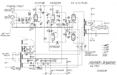
I found a schematic for a Hohner Orgaphon 45 MH (attached). Close enough?
Very cleanly drawn schematic, voltage doubler power supply, individual (fixed) bias adjustments for each output valve. Sadly, no indicated voltages, no information about transformers (voltages, impedances).
I don't understand German, so if anyone spots information here that I've missed, please do share it in this thread!
-Gnobuddy
Attachments
From radiomuseum, it supposes to have <1% distortion at 40W!Of course, just raising the THD specs allows for more output power from the same tubes in the same configuration.
The voltages used in the MH41 were: Ep =380V, Eg2=220V, Eg1=-25V, which suggests that the tube was very conservatively rated.Sadly, no indicated voltages, no information about transformers (voltages, impedances).
Amazing! 40 watts from a pair of 12-watt valves - without melting them - sounds like the sort of thing only Tubelab George regularly manages to pull off!
Well, that's about the same we read in EL34 datasheets - 100 watts from a pair of 25-watt tubes
!Btw, Hohner seem to have loved TV tubes in musical instrument amplifiers. There's also an amp with two PL509's as finals!
Best regards!
Last edited:
Thanks for posting the information needed guys, that Hohner 50 really got me rolling and thinking... Currently I am working on some project (sort off I guess), i am making an parallel single ended amp because that is my only choice (I have a huge 15W output transformer for single ended and it has different primaries)
I am thinking to combine a two 12AY7 in the preamp stage of single ended, and two power EL86 tubes in parallel (that's the original idea)
By the way I have read that it is not a wise idea to put an EL86 in an place of EL84 because of the screen differences and plate voltage... the problem with the EL86 is... you can drive their plates to some higher voltage than 275v (for overdrive) but you MUST protect that screen that must NOT go higher than 200v. So yeah that's the problem.
But always, thanks for replying to this boring one.
Oh no, this EL86/PL84/UL84 thing isn't boring at all! Due to their lower µg2g1, lower internal plate resistance and higher slope of the left limiting line of the bunch of plate curves, one can easily pull much more power form a pair of those tubes, in comparison with the much more common EL84/6BQ5.
Best regards!
Best regards!
6N1P tube in a guitar amp
Hi all, back with another stupid question, what do you think about ECC88 or 6N1P tube in a preamp stage of a parallel single ended guitar amp?
So... I am building a PSE amp with 2x EL86 and 2x ECC88, is that a wise idea?
I know that ECC88 is not a tube for harsh distortion and all that Marshall style amps... But i read all the datasheets on the tube and gathered some basic information about it, and at last i need somebody's opinion on that tube before i start building anything...
(Sorry to bother so much on everything guys, but i am still a beginner that needs somebody's help.)
Thanks in forward for replying...
Hi all, back with another stupid question
, what do you think about ECC88 or 6N1P tube in a preamp stage of a parallel single ended guitar amp? So... I am building a PSE amp with 2x EL86 and 2x ECC88, is that a wise idea?
I know that ECC88 is not a tube for harsh distortion and all that Marshall style amps... But i read all the datasheets on the tube and gathered some basic information about it, and at last i need somebody's opinion on that tube before i start building anything...
(Sorry to bother so much on everything guys, but i am still a beginner that needs somebody's help.)
Thanks in forward for replying...
The 6N1P dual triode is something between the 12AU7 and the 12AT7. So it should work. But don't expect too much gain from a single stage.
The ECC88 is quite another tube and is about the same as the Russian 6N23P. I never did experiments with this one in a guitar amplifier.
Best regards!
The ECC88 is quite another tube and is about the same as the Russian 6N23P. I never did experiments with this one in a guitar amplifier.
Best regards!
Not a big problem, really. It just means the power supply needs to provide two different voltages, one for screens, one for anodes.the problem with the EL86 is... you can drive their plates to some higher voltage than 275v (for overdrive) but you MUST protect that screen that must NOT go higher than 200v. So yeah that's the problem.
One way this can be done is to use a transformer that puts out about 200 V DC after rectification, for the screens. Then use the same transformer to feed a voltage doubler circuit, which spits out about double the DC voltage, i.e. 400V, for the anodes.
I was on the Aussie Guitar Gearheads forum for a while, and it seems a number of vintage Australian valve guitar amps used exactly this approach - a voltage doubler power supply, with the screens of the output valves fed about half the voltage that the anodes were getting.
There is more than one way to build a voltage doubler. If you are unfamiliar with these, Google should turn up some information. Just get someone here to check the schematic before you build, because there are some wrong schematics floating around the 'Net.
A voltage doubler was a simple, affordable, and practical solution back in 1965 or so. Today, there are other equally simple solutions, because we have access to electronic components that didn't exist in 1965. You can simply use a high-voltage power MOSFET and a couple of resistors to drop the B+ voltage to 200V for the screen grids.
I have never seen anyone actually do this in a guitar amp, but there is absolutely no reason why it shouldn't be done. You may be aware of the "VVR" circuit, which uses a power MOSFET to lower the B+ voltage in a valve guitar amp, to enable overdrive at lower volumes. That same VVR circuit will do the trick to lower screen grid voltage, the only difference being that you want to set the VVR to 200V (or whatever your target screen voltage might be), and feed only the output screen grids from it, and not the rest of the amp.
If you try this, you could get away with a smaller MOSFET and smaller heat-sink than a traditional VVR, since the screen grids draw maybe one-fifth as much current as the anodes do. The datasheet should turn up more accurate numbers, if desired.
-Gnobuddy
Last edited:
> i am still a beginner
> i need somebody's opinion on that tube before i start building anything...
Beginners should not wander unexplored country.
Beginners *should* Build Something!!
There are 60+ years of amplifiers which were pleasing to musicians. There is no shame in building something pretty-much like what already works.
If this is truly your path, you *will* build more amplifiers, each time wandering a little further away from past designs. Or maybe re-inventing things that other builders tried and rejected. But "an amp is an amp". Most of the basics are all the same. Trying a different tone-control, or using a different tube, is usually just few wires moved.
Before everybody gets worked up and in a sweat, the 50 used four output tubes.
1965 Hohner Orgaphon 50 MH (4xPL84)
Vintage Amps Bulletin Board • View topic - 1965 Hohner Orgaphon 50 MH (4xPL84)
Might be worth a look
Index of /Roehren-Geschichtliches
1965 Hohner Orgaphon 50 MH (4xPL84)
Vintage Amps Bulletin Board • View topic - 1965 Hohner Orgaphon 50 MH (4xPL84)
Might be worth a look
Index of /Roehren-Geschichtliches
Ah. That explains a lot!...the 50 used four output tubes.
Theoretical maximum efficiency of a class B stage is Pi/4, about 78.5%. With 100 watts in from the power supply, you'd have 78.5 watts to the speaker, and 21.5 watts to be dissipated between the two output devices; that's less than 11 watts dissipation per output device.
In a perfect world, then, a pair of 12 watt output devices should be able to pump out something like 80 watts.
Our world is very definitely imperfect, but 45 watts from two 12W output devices seemed plausible, even if unusual for a valve circuit. (It would require about 65% efficiency, ignoring power taken by the heater and screen grids.)
-Gnobuddy
It started out as the Orgaphon 50 - see Kay Pirinha's post #5.We are not discussing the Orgaphon 50MH though... the 45MH only used two PL84's to get at least 40W.
I searched for a schematic for the Orgaphon 50, but came up empty. I did find one for the Orgaphon 45, so I posted that one, and asked "close enough?", because I wasn't sure how close the two circuits were to one another. The 45 uses only two output valves.
Now I'm quite confused. Do we know the rated output of the Orgaphon 45? Was there really a 40-watt Orgaphon that used only two PL84s, or did the 40-watt Orgaphons use 4 output valves?
-Gnobuddy
Thanks! Okay, my feet are on solid ground again!According to radiomuseum, the MH45 is rated for 45W.
Only if they are four 6AK6s or 50C5s!In any case, there is nothing special about getting 40W with 4 tubes, is there?
-Gnobuddy
You just told me about an interesting amp using interesting valves that achieves an interestingly high output stage efficiency. You did me a favour, nothing to be pardoned for!Please pardon me for having brought up the confusion.
-Gnobuddy
- Status
- This old topic is closed. If you want to reopen this topic, contact a moderator using the "Report Post" button.
- Home
- Live Sound
- Instruments and Amps
- What do you think about this tube schematic?