Cortez said:Hi Mike !
ISo I think the conventional layout, what Mike wanted to improve
is when there are only the wires #1 and #2, because then noise
currents would create voltage on the resistance of wire #2.
And what Mike is using: #3 to route everything, noise and interference
from the interconnect cable's ground wire to our main GND reference
point with a low impedance path, and to the PCB we are using wire #1 (wire #2 isnt there).
Am I right ?
Hi all,
I just woke up so I'll discuss more later, but I wanted to point out that there is no wire # 1 in Cortez;s image. These are images of my most recent creations and I believe I indicated that it was different than the original simplified suggestion in my first post.
Without going into to much detail now, this approach works if you think about where noise being picked up on the interconnecting cables and where the noise circulating between component supplies can go (between amp/preamp, for example).
This approach bypasses the noise to the tranformer ground, avoiding the input circuitry loop presenting a clean ground and a solid reference for the signal. The regulated supply loops are handled the same.
If you notice the transformer grounds are separate and both bonded to the same central chassis ground.
More once I wake up and read through the rest of the postings.
Mike.
AndrewT said:Hi,
what if two or more pieces of interconnected audio equipment have the safety ground used as the main/only audio ground?
I think you end up doing the trick of having interconnects with the shield only connected at one end. WFM once.
More general info on grounding in Rane's AN110.
cpemma said:
I think you end up doing the trick of having interconnects with the shield only connected at one end. WFM once.
Only internally, all of the connections between system components are normal interconnects.
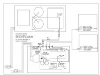
I pu together an drawing to answer the earlier question about the safety grounds.
Mike.
Attachments
Cortez said:Hi Mike !
I guess your design has 2 specialites, so lets separate them:
1) Using flat cables, improves high frequency behaviour based on the skin effect.
>>>Yes, It creates a low noise reference/return loop for the input stage.
2) grounding the input directly from the RCA to the main GND
>>>This very effectively bypasses high frequency noise around the sensitive signal path.
There is 3 GND points on this model:
>>> Yes I would call them return loops:
So I think the conventional layout, what Mike wanted to improve
is when there are only the wires #1 and #2, because then noise
currents would create voltage on the resistance of wire #2.
And what Mike is using: #3 to route everything, noise and interference
from the interconnect cable's ground wire to our main GND reference
point with a low impedance path, and to the PCB we are using wire #1 (wire #2 isnt there).
Am I right ?
>>>Correct.
AndrewT said:Hi Mikeb,
Is the first statement true?
What are the consequences of the first and second?
Can we have your answer?
>>> Yes the first statement is true. Technically there should be no signals routed through the safety ground, but then RF noise choses it's owen path of least resistance. My layout attempts to remove any path through the signal returns.
>>>As for the second, (hopefully my system layout picture was readable. I tried using my schematic entry program and I wasn't sure how it ended up in the post) If multiple safety grounds are used they need to be plugged into the same power. There is no loop back through the circuitry and little chance for a noise voltage to be developed by this connection.
>>>The biggest problem will be the voltages induced in the chassis by the amp and preamp transformers seeing this connection as a loop.. This I have always minimised through hooking up the transformers to minimize any AC voltage between the amp and preamp with no cables connected between them.
Mike
!:
> The high frequency is exactly what good PSU design strives to eliminate.
Well I think its relative. Just the voltage level should be constant, DC,
but to achieve this, our PS have to react to the high frequeny load fast,
and should need "high speed energy transmission" on thw rails. If our PS is too slow,
based on inductance, etc, the voltage would first fall and then rise like at an inductor.
This modell is specially real at high freqs, where the small inductances gets high, and
this could lead to oscillations, etc. So a DC PS should also be fast in my view.
Mike:
> I wanted to point out that there is no wire # 1
So then your design has just wire #2 and #3 ?
Cause later you said my post is correct with #1 + #3.
Wich one is actually your layout then ?")
> this approach works if you think about where noise
> being picked up on the interconnecting cables and where
> the noise circulating between component supplies can go
So, in your design the point is: everything from the input ground goes
directly to the main ground, so it is not going through the PCB, right ?
Otherwise your chassis is connected to the safety earth ?
To your drawing: its too small, I cant read the textes.
> The high frequency is exactly what good PSU design strives to eliminate.
Well I think its relative. Just the voltage level should be constant, DC,
but to achieve this, our PS have to react to the high frequeny load fast,
and should need "high speed energy transmission" on thw rails. If our PS is too slow,
based on inductance, etc, the voltage would first fall and then rise like at an inductor.
This modell is specially real at high freqs, where the small inductances gets high, and
this could lead to oscillations, etc. So a DC PS should also be fast in my view.
Mike:
> I wanted to point out that there is no wire # 1
So then your design has just wire #2 and #3 ?
Cause later you said my post is correct with #1 + #3.
Wich one is actually your layout then ?
> this approach works if you think about where noise
> being picked up on the interconnecting cables and where
> the noise circulating between component supplies can go
So, in your design the point is: everything from the input ground goes
directly to the main ground, so it is not going through the PCB, right ?
Otherwise your chassis is connected to the safety earth ?
To your drawing: its too small, I cant read the textes.
Cortez said:!:
> The high frequency is exactly what good PSU design strives to eliminate.
Well I think its relative. Just the voltage level should be constant, DC,
but to achieve this, our PS have to react to the high frequeny load fast,
and should need "high speed energy transmission" on thw rails. If our PS is too slow,
based on inductance, etc, the voltage would first fall and then rise like at an inductor.
This modell is specially real at high freqs, where the small inductances gets high, and
this could lead to oscillations, etc. So a DC PS should also be fast in my view.
High frequency shunt to ground, yes, but not +- rails.
Lowest impedance reasonably possible, also yes.
Rapid changes in voltage, no. If the PSU voltage dips but does so somewhat linearly, the reasonably fast opamp/chipamp can adjust (save for lower peak output and/or distortion at that maximum ouput level), but if the frequency of voltage change is rapid, a greater problem exists. It is same thing as having a high speed chip with no close/fast decoupling caps, the resultant problem is high frequency modulations on the power rails that we want to remove.
So there's that trade-off on low impedance and fast loop PSU response to voltage change, but you want the delivered power to not show this high frequency noise, nor to allow pickup and transmission of any other HF noise, nor to allow transmission of HF noise from one component to another if there are multiple chips sharing a PSU subsystem. The close decoupling helps a lot to remove HF components of power, but it goes back a bit to what I was saying earlier that in the end you want the least HF possible, even if the PSU is fast.
Cortez said:!:
Mike:
> I wanted to point out that there is no wire # 1
So then your design has just wire #2 and #3 ?
Cause later you said my post is correct with #1 + #3.
Wich one is actually your layout then ?
>
Otherwise your chassis is connected to the safety earth ?
To your drawing: its too small, I cant read the textes.
>>>Cortez,
The posts are (i'm) getting confused between my original post and the concept that the images I sent conveyed.
I interperted your reply to be discussing the 1-3 return I originally posted, not the version I'm using with 1 missing in the images I posted. This is my mistake.
Confusing this as well are the posts by ! (?) talking about power supplies rejecting high frequencies by design... (Ground is a whole other world.)
My focus and comments have all been related to grounding and the path for both noise and return currents back to the common reference point in the power supply. By doing this the noise floor is lowered and the susceptability to noise (RF - hum) pickup is reduced.
I guess that, because it all makes sense to me, I'm leaving out pieces of the discussion that would help to clarify my meaning here. Or, the common understanding of grounding is making this all not fit. Who knows?
I'll re-do the layout so it's readable and we can see where this goes from there.
As you can figure, I'm a newbie to this stuff.
And Yes, the chassis and the circuit ground can be connected to the safety ground without any sonic penalties...
Mike.
!:
> Rapid changes in voltage, no.
I didnt say that. If there is a rapid changing load, we can provide
the DC only when we react as fast as possible, and that requires
fast transmission rails from the PS to the load.
Certainly not the voltage at the rails shoud change fast, but to
not change, we have to fulfill the load's energy requirements fast.
Imageine, if the rails had a large inductance (they are slowly reacting)
the voltage level at the and will be changing, cause the PS is separated
through this slow wire and cant force his constant voltage goals.
What you are talking about is high speed noise, what we really shoud avoid.
Its two conflicting requirement. Exactly thats why local decoupling is important, I guess.
May be high freqs can be hold at there and only slower currents are going from the main PS caps.
As you also wrote on your 2nd section.
But on the other hand, lets not forget, that yes, the voltage should
constant, but the current from a PS will be rapidly changing all the time.
Maybe a flat cable is more appropriate to achieve this, dont know...
But that is getting a little OFF now, sorry.
Mike:
Ok, so there was 2 different layout discussed here.
So lets clear it now, your suggested latest design is when
wires #2 and #3 are used only, right ?
Otherwise with a layout like this the signal ground can go back to
the source only through our PS, right ? Isnt that a possible problem ?
> And Yes, the chassis and the circuit ground can be connected
> to the safety ground without any sonic penalties...
But in that case when an other device has also an earthed GND,
the signal ground wires could transmit earth currents too, couldnt they ?
Cortez said:!:
> Rapid changes in voltage, no.
I didnt say that. If there is a rapid changing load, we can provide
the DC only when we react as fast as possible, and that requires
fast transmission rails from the PS to the load.
Reacting as fast as possible requires a low impedance, but not high frequency. That's why there are always other capacitors in the whole-supply-chain, not just local decoupling caps.
Certainly not the voltage at the rails shoud change fast, but to not change, we have to fulfill the load's energy requirements fast.
Imageine, if the rails had a large inductance (they are slowly reacting) the voltage level at the and will be changing, cause the PS is separated through this slow wire and cant force his constant voltage goals.
While that is a problem, it is a less severe problem than high frequency. When voltage is dipping in a regular low frequency fashion it will mainly effect the peak output possible, the feedback (usually present- we are in the chipamp forum) will catch that with small % error to correct. When there is high frequency, even if the voltage change is less, there is a continual higher % error rate to correct. In other words, smooth power 1 volt too low beats half a volt higher but high frequency ripple to keep it there. That is, until you try to crank that output up and it clips. I think that not much of a problem because there should always be a couple volts to spare in the target PSU design.
What you are talking about is high speed noise, what we really shoud avoid. Its two conflicting requirement. Exactly thats why local decoupling is important, I guess.
I'm talking about high frequency anything - ripple induced by other parts, by the chipamp itself, by the PSU, but pickup on the power leads, the cause may not matter so much as possible results. However, there are some that seem to even like this kind of modulated distortion, DIYAudio is home to a few who even like switching PSU for some amps which is a big no-no for clean sound no matter how much some would like to argue otherwise... that if they "like" it, that is supposed to mean it's automatically clean by some magical property too.
May be high freqs can be hold at there and only slower currents are going from the main PS caps. As you also wrote on your 2nd section. But on the other hand, lets not forget, that yes, the voltage should constant, but the current from a PS will be rapidly changing all the time. Maybe a flat cable is more appropriate to achieve this, dont know...
But that is getting a little OFF now, sorry.
It seems a timely thought to have. Flat high-frequency path to ground to kill HF noise should do good by the circuit. Flat high frequency voltage rails are not a good thing, are only tolerable in some instances because there is a good ground plane adjacent.
That's just idealisim though, it doesn't mean an amp wouldn't be great using some other strategy. My main point is that given a choice, the better alternative is to avoid high frequency in the PSU, let the caps take care of the supply and address voltage depression though lower impedance, not wide flat traces without some close ground planes.
> Reacting as fast as possible requires a low impedance, but not high frequency.
I dont see this as two separate things. Obviously impedance could dependent on frequency.
Under high freqency, I mean low impedance at high freqs = low inductance.
Dont you agree with this ?
When the rails is inductive, it could get out of phase, and this
can lead to oscillation specially with feedback in the amp.
Banned
Joined 2002
Does any one have any ideas for this problem.
I have to mini a's ( not mine ) when they are plugged into a source they get a hum BUt if i disconnect one channel the hum goes away in both if i put it back on the hum is back. this happens if i remove a input on either channel. I have tried every thing separating psu's separating sources cables speakers etc etc Even moved the transformer around put a piece of copper plate around it and the psu. Still same thing.
I have to mini a's ( not mine ) when they are plugged into a source they get a hum BUt if i disconnect one channel the hum goes away in both if i put it back on the hum is back. this happens if i remove a input on either channel. I have tried every thing separating psu's separating sources cables speakers etc etc Even moved the transformer around put a piece of copper plate around it and the psu. Still same thing.
Cortez said:> Reacting as fast as possible requires a low impedance, but not high frequency.
I dont see this as two separate things. Obviously impedance could dependent on frequency.
They are two separate things. Inevitably with any high(er) speed IC, the closer you get to the component the higher the frequency of the ripple, but we are considering the other end, the supply itself needs not have this high frequency deliverly potential, only a low impedance. The high(est) frequency needs are low current and are handled by the decoupling caps and should not be (ideally) allowed to be transmitted back and forth on the entire PSu.
Under high freqency, I mean low impedance at high freqs = low inductance.
Dont you agree with this ?
I agree only in some contexts. Only local to the chip does the PSU need be low impedance to high frequency. That's the role of the immediate-vicinity decoupling caps. The main PSU should not attempt to transmit at such frequencies as it would swamp the decoupling and induce rail-modulated distortions.
When the rails is inductive, it could get out of phase, and this
can lead to oscillation specially with feedback in the amp.
That's why the local decoupling caps are so important, not just ~ 0.1uF but at least a minimal value (as seen on GC for example) was 100uF close to the amp, if not higher-plus-snubbers. The path between this 100uF cap and chip must then be capable of high frequency but not between the main PSU and this stage. The degree to which this frequency can be reduced depends on # of stages in PSU and decoupling along the way to that point in the circuit.
Hi Mikeb,
Plug two pieces of equipment into the same dual outlet mains socket each with their own safety ground used as the only multi-purpose ground as you have described ( I cannot read your diagram). Interconnect them with a conventional audio coax using the RCA ground at each end to the chassis ground and it is almost guaranteed to generate hum. This is completely at odds with your statement
I have a feeling you have experimented with your multi-purpose safety ground on the power amp and reached a preliminary conclusion that the idea of this simple grounding can be applied to all equipment without realising that all your other connected equipment was properly earthed and grounded using separated safety and audio grounds. The correct wiring of the other equipment saved your mis-wired amp from showing the symptoms you have managed to hide.
Please come back and confirm how you have achieved your magic.
I cannot believe this, it is misleading, no, I will go further, it is completely wrong......If multiple safety grounds are used they need to be plugged into the same power. There is no loop back through the circuitry .....
Plug two pieces of equipment into the same dual outlet mains socket each with their own safety ground used as the only multi-purpose ground as you have described ( I cannot read your diagram). Interconnect them with a conventional audio coax using the RCA ground at each end to the chassis ground and it is almost guaranteed to generate hum. This is completely at odds with your statement
and little chance for a noise voltage to be developed by this connection.
I have a feeling you have experimented with your multi-purpose safety ground on the power amp and reached a preliminary conclusion that the idea of this simple grounding can be applied to all equipment without realising that all your other connected equipment was properly earthed and grounded using separated safety and audio grounds. The correct wiring of the other equipment saved your mis-wired amp from showing the symptoms you have managed to hide.
Please come back and confirm how you have achieved your magic.
But even if we have decoupling capacitors, there will beOriginally posted by ! That's why the local decoupling caps are so important
high freqency between the main PS and the local caps.
For example when a GC produces a 20kHz sine, this will appear
also on the main PS raild, and not just on the local caps, right ?
AndrewT said:Hi Mikeb,
I cannot believe this, it is misleading, no, I will go further, it is completely wrong.
Plug two pieces of equipment into the same dual outlet mains socket each with their own safety ground used as the only multi-purpose ground as you have described ( I cannot read your diagram). Interconnect them with a conventional audio coax using the RCA ground at each end to the chassis ground and it is almost guaranteed to generate hum. This is completely at odds with your statement
>>> This has been my point from the start. If the noise voltage created by the loop does not circulate through the gain stages, and the ground is a low impedance, clean ground, there is no hum.
>>>The problems are usually created poor grounding starting at the transformer. What I proposed was a means to control both the return paths and the effectiveness of the ground net.
>>>The definition of ground, as I interpert it is, an unvarying reference for the supplies and hence the circuitry. One should be able to sink or source any amount of electrons from ground and not upset it's basic charge, which relative to the rails should be zero (at all frequencies of interest). In the real world one can only achieve degree of success in this. When this does not happen the ground becomes another input into your circuit.
Which is why I attempt to control the return paths as well.
I have a feeling you have experimented with your multi-purpose safety ground on the power amp and reached a preliminary conclusion that the idea of this simple grounding can be applied to all equipment without realising that all your other connected equipment was properly earthed and grounded using separated safety and audio grounds. The correct wiring of the other equipment saved your mis-wired amp from showing the symptoms you have managed to hide.
>>> This is an interesting set of comments. I've spent 30 years experimenting with what I call the circuit environment. The first 15 in audio, the second in semiconductor manufacturing. Specifically investigating: power supplies, grounding and layout. Professionally, I develop process monitoring applications where my circuits need to function flawlessly in the presence of strong RF fields. I'm still employed and not starving.
>>>My involvement in this thread was purely with the intent to throw a concept out there and a suggested implementation. Hopefully to discuss the finer points of implementation and get feedback based on results. I thought the chip amp approach would minimize the number of internal circuit related layout problems. So far the response has been it can't work.
Please come back and confirm how you have achieved your magic.
>>>I've been trying. Obviously it's magic.
Hi Mikeb,
glad to hear from you.
Any chance you could re-post a legible version of your grounding scheme so we can see if it is magic or just a clever way to connect the grounds?
ps that's a difficult read, mixing quotes with new postings. You're getting as bad as Beppe before he realised there was a better way.
Cortez said:
But even if we have decoupling capacitors, there will be
high freqency between the main PS and the local caps.
For example when a GC produces a 20kHz sine, this will appear
also on the main PS raild, and not just on the local caps, right ?
It would be mitigated by the local decoupling caps as much as the rest of the design (space and budget) allows. This is why there are capacitors, one of their primary purposes.
AndrewT said:Hi Mikeb,
glad to hear from you.
Any chance you could re-post a legible version of your grounding scheme so we can see if it is magic or just a clever way to connect the grounds?
ps that's a difficult read, mixing quotes with new postings. You're getting as bad as Beppe before he realised there was a better way.
Thanks for asking about re-posting the layout. I have to redraw it so I needed a little incentive to feel that I wasn't just ******* in the wind.
It'll be posted sometime tomorrow. Mike.
Hi Mike !
Obviously you didnt noticed my Q to you while I was OFFing, sorry!
So there was 2 different layout from you, discussed here.
Let's clear it now, your suggested latest design is
when wires #2 and #3 are used only withou #1, right ?
http://www.diyaudio.com/forums/attachment.php?s=&postid=900011&stamp=1145856645
But with a layout like this, the signal ground can go back to the source (RCA)
only through our PS (through wire #2) and after that on the noisy wire #3, right ?
Isn't that a possible problem ?
Or #3 and #1 withour #2 is also a good way of grounding right on this base ?
Because then we would have the low impedance grounding (#3) far from the PCB but we also
have a direct, separate, "clean" wire from the PCB to the source (RCA) ground (#1).
> And Yes, the chassis and the circuit ground can be connected
> to the safety ground without any sonic penalties...
But in that case when both device is earthed at GND, the signal
ground wires could transmit earth currents too, couldnt they ?
Otherwise I would like to thank you very much your tenacity to answering me/us !
!:
> It would be mitigated by the local decoupling caps
So in your opinion, there wont be a 20kHz load to the main caps ?
That depends on the load, amount and speed of local decoupling as well as layout. Yes it's quite possible you can get 20KHz ripple across an entire supply, but it should not be a goal and the magnitude of it should be reduced.Originally posted by Cortez So in your opinion, there wont be a 20kHz load to the main caps ?
- Status
- This old topic is closed. If you want to reopen this topic, contact a moderator using the "Report Post" button.
- Home
- Amplifiers
- Chip Amps
- What distance should a toroidal be from the audio circuit?