cpemma said:
There's a decent case for 2 bridges if you're going to regulate the supply; identical regulators can be used on each positive line before tying one to the other's negative to form your + 0 -.
I've never seen that approach. I'm assuming this approach allows identical regulators.? Is there another reason?
Mike.
No hum here
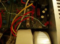
With this amp I can hear no electrical hum, even when I stick my ear directly in front of the loadspeaker elements. (It is 4x P-A´s QRP 02)
But I have some mechanical hum in the toroids.
May this introduce distortion even if I hear no hum?
With this amp I can hear no electrical hum, even when I stick my ear directly in front of the loadspeaker elements. (It is 4x P-A´s QRP 02)
But I have some mechanical hum in the toroids.
May this introduce distortion even if I hear no hum?
Attachments
gaplessophile said:
About your description of how an amp should be grounded, could you explain why it's good for the input jacks to be grounded to the chassis, if the transformer is also? I've read about how it's good to keep the signal ground and the power ground separate. Also, with the input jacks grounded this way, should they still have a ground wire going from them to the amplification circuit, along with the signal wire?
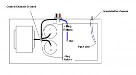
The power transformer ground is the 0 volt reference for everything that happens in the amp. By grounding the transformer at a central point, and returning the output grounds, the regulator grounds and the signal grounds to it, any interaction between them is minimized. The reason I use the chassis as a return (for only the input circuit) is because any interference that is impressed on the interconnect cable shields or ground currents circulating between other parts of the system appear on this ground as well. By taking any other path or by using a wire rather than the low inductance of the chassis, all of this noise becomes injected into the ground reference to both the input side and the feedback network in the amplifier. Sonically this creates a congested sounding noise floor, a two dimensional quality. It can also cause stability problems and a sensitivity to mains pickup.
I'll attach a basic picture
Attachments
MikeBettinger said:I've never seen that approach. I'm assuming this approach allows identical regulators.? Is there another reason?
(a) http://www.tcaas.btinternet.co.uk/jlhnewps.htm an early example but I've seen several discrete ones here & elsewhere.
(b) There are other opinions like every other audio choice.
cpemma said:
(a) http://www.tcaas.btinternet.co.uk/jlhnewps.htm an early example but I've seen several discrete ones here & elsewhere.
(
Interesting, I'll have to give this a try, not for an amp supply, but a preamp I think; although I have been tempted to build a JLH to see what the fuss is about.
Thanks for the input.
Mike.
Re: No hum here
If you can't hear it, then the hum is not there to affecting anything. High frequencies can hide in the background and degrade performance, but that's not the case here.
Mike
AndyB said:With this amp I can hear no electrical hum, even when I stick my ear directly in front of the loadspeaker elements. (
May this introduce distortion even if I hear no hum?
If you can't hear it, then the hum is not there to affecting anything. High frequencies can hide in the background and degrade performance, but that's not the case here.
Mike
chipco3434 said:Ain't pretty, but dead quiet...
On my A30/Mini, I shielded the toroids using a stainless sheet metal enclosure. To the inside of that hat, I applied double stick tape and lined the hat with some leftover galvanized flashing material covered by single sided aluminum tape to make it pretty. It's VERY quiet.
I'm glad that it's quiet but this is a bad example. Stainless does not shield from magnetic fields much at all, and the strongest point in the magnetic field in a toroid is axially, straight up through the center of the toroid. It's like a rod of intense magnetic field relative to any and all other places around the toroid.
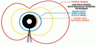
Here is the typical horizontal field from toroid, horizontal since most lay out the amp this way. One of the main things to learn from the picture is to put a metal (with higher iron content if not mu) skirt around the transformer. Some are made like this, but they are obvious enough as the metal is clearly visible on the outside even though it may be under the outer wrapping. Image taken from
nuvotem.com
Attachments
MikeBettinger:
And what about this: "ground currents circulating between other parts" ?
So I dont get, whats the point, to use the chassis vs a wire. Sorry.
Could you please draw a schematic to illustrate electronically the difference with RLC items ?
What kind if interference do you mean ? RF from outside ?The reason I use the chassis as a return (for only the input circuit)
is because any interference that is impressed on the interconnect
cable shields or ground currents circulating between other parts
of the system appear on this ground as well.
And what about this: "ground currents circulating between other parts" ?
So I dont get, whats the point, to use the chassis vs a wire. Sorry.
And when you use the chassis, why doesnt happen the same ?By taking any other path or by using a wire rather than the low
inductance of the chassis, all of this noise becomes injected into the ground reference
Could you please draw a schematic to illustrate electronically the difference with RLC items ?
You can always put an earthed wall between the two. Some commercial amps use the heat-sink as shielding.
Works pretty well for some of us DIYers, too.
Banned
Joined 2002
I think i'm going to get a steel tube and get a top welded on top of it so the wires can hang out . the way the case is designed is that the psu stacks on top of the transformer so this might be the problem. I have never run into this type of problem so it is a experience for me. Right now it is a project for a friend.
Jase
Jase
Stainless does not shield from magnetic fields much at all,
Yes sir. I understand. It's just pretty to look at relative to a ferrous material that must be finished. The shielding is provided by the galv flashings that line the inside of the "hat".
Guys,
One of the beauty things about a toroid is that they don't radiate much in the way of magnetic fields... this, in turn, means they don't pickup (recieve) that much either. This fact, if anything, is their claim to fame.
Now electrostatic fields are a whole 'nother matter. In fact, toroids can be worse in this regard because the windings, and their capacitive coupling to anything near them, are plainly exposed on the outside of the tranformer.
What you need is electrostatic shielding... just something conductive. Put a grounded metal can over the toroid... be sure not to make a complete circuit (shorted turn) by putting an uninsulated bolt through the middle... and you're good to go. You can put that tranny just about a close as you want to.
From what I have seen... a tuna fish can would do wonders here.
Cortez said:What kind if interference do you mean ? RF from outside ?
And what about this: "ground currents circulating between other parts" ?
So I dont get, whats the point, to use the chassis vs a wire. Sorry.
And when you use the chassis, why doesnt happen the same ?
Could you please draw a schematic to illustrate electronically the difference with RLC items ?
I guess I should have been more clear, sorry. The inteference I'm speaking of is any RF the interconnect cables are subjected to, any magnetic interference (transformer fields, A.C wiring, speaker wiring, etc.). The ground currents I mentioned are between other system components, ie: preamp, tuner etc.
The chassis metal provides a very low impedance path extending into the mhz. This provides two benefits. First, since any interfering signal's only attraction is to ground (and to get there through the easiest path), the chassis effectively provides that path (around the circuitry). The second advantage is that the ground reference of the power supply needs to be availible as a zero volt reference and a return path for the input circuitry and feedback. By using a wire this is not necessarilly the case. Both noise currents and return currents are affected by the wire's impedance. both can create noise on the circuit's ref/return and show up in the amp's output.
The logic behind this is the same that applies to the use of ground planes in all high performance electronics.
I observed this layout years ago in the second version of the original Ampzilla and have experimented with and used it with all type of amp circuits with consistant results.
Mike
Mike,
> The chassis metal provides a very low impedance path extending into the mhz.
But a thick wire can also do this, cant ?
Or its important that the chassis surrounds the circuits ?
> any interfering signal's only attraction is to ground
Otherwise its also a noise source when a signal affects a PS rail
or just the GND is sensitive to this ?
> Both noise currents and return currents are affected by the wire's impedance.
So the point is to have a GND wire with the minimum resistance as possible ?
Cortez said:Mike,
> The chassis metal provides a very low impedance path extending into the mhz.
But a thick wire can also do this, cant ?
Or its important that the chassis surrounds the circuits ?
>>The skin affect limits this as the frequency goes up. The chassis or shielding doesn't come into this effect.
> any interfering signal's only attraction is to ground
Otherwise its also a noise source when a signal affects a PS rail
or just the GND is sensitive to this ?
>>If the noise signal is on a supply line then it is using it as a path to ground. This current is why it shows up on the signal.
>> A supply line can also be a low impedance path back to ground.
> Both noise currents and return currents are affected by the wire's impedance.
So the point is to have a GND wire with the minimum resistance as possible ?
>>Minimum resistance at the frequency of the interference for electrical noise.
Mike.
> The skin affect limits this as the frequency goes up.
> The chassis or shielding doesn't come into this effect.
So a large cross sectional area with a flat shape is the best ?
Flat cables are better in high freqs based on skin effect ?
> If the noise signal is on a supply line then it is using it as a path to ground.
...
> A supply line can also be a low impedance path back to ground.
Directly through the rails or through the circuit ?
> Both noise currents and return currents are affected by the wire's impedance.
So the point is to have a GND wire with the minimum resistance as possible ?
> Minimum resistance at the frequency of the interference for electrical noise.
So a low impedance would be the best at high frequency, cause these noise are mainly at high freqs.
Hmm, maybe a good and small cap could be used somehow as a high freq grounding ?
Cortez said:Hmm, maybe a good and small cap could be used somehow as a high freq grounding ?
That way is common on the mains input to the transformer primary, with 10n-100n film caps from L & N to safety earth, and across L & N.
! said:
I'm glad that it's quiet but this is a bad example. Stainless does not shield from magnetic fields much at all, and the strongest point in the magnetic field in a toroid is axially, straight up through the center of the toroid. It's like a rod of intense magnetic field relative to any and all other places around the toroid.
are you sure about the direction of stray magnetic field direction?
according the Ampere's Law (know as the right hand rule), I don't see why the field direction is straight up through the center of toroid.
- Status
- This old topic is closed. If you want to reopen this topic, contact a moderator using the "Report Post" button.
- Home
- Amplifiers
- Chip Amps
- What distance should a toroidal be from the audio circuit?