Oh, good to hear about. Just knew, that there was a paper, older one from Nelson, containing some general information. So this is good news. Timing from rumor to execution might be tempting for us greedies.I hear rumors of a possibility of a discrete from Nelson.
Whammy 5W class a power amp maybe? For 100db+ speaker. To have a low power alternative to ACA without lytics in order to power mids and tweeters in a multi way system. Just an idea - and by the way I really like my ACA.
I hear rumors of a possibility of a discrete from Nelson.
Exciting....
") Do "rumors" tell anything more, yet?
Do "rumors" tell anything more, yet?Hi Guys,
Need your help just finished the Amp and there seems to be something wrong my Right Channel. My Voltage rails are fine +16.7v & -16.7v. However my right channel is not putting out much power at all, and its square wave looks sick...
The only non-standard thing I have added is a feed from R10 & R14 to the v12 LED (power Switch) with a 4.7K limiting resistor on the R10 +V link side.
1Khz Signwave 1vp-p Right channel is ~2mV and Left is 100mV

1Khz Squarewave 1p-p - Right channel is 10mV and Left is 100mV


Any ideas where to look next, could this be an issue with my OP-AMP its a Burr-Brown OPA2134PA without the 100 pF caps.
Mark.
Need your help just finished the Amp and there seems to be something wrong my Right Channel. My Voltage rails are fine +16.7v & -16.7v. However my right channel is not putting out much power at all, and its square wave looks sick...
The only non-standard thing I have added is a feed from R10 & R14 to the v12 LED (power Switch) with a 4.7K limiting resistor on the R10 +V link side.
1Khz Signwave 1vp-p Right channel is ~2mV and Left is 100mV
1Khz Squarewave 1p-p - Right channel is 10mV and Left is 100mV
Any ideas where to look next, could this be an issue with my OP-AMP its a Burr-Brown OPA2134PA without the 100 pF caps.
Mark.
Last edited:
I don’t know how to edit previous so I post a new one.
I almost finish my WHAMMY with previous version PCB. Hook up the power socket and wire and I am done with this project. I tried to connect the power everything seems fine. I hear no noise of any kind. Just wondering if I have to install the capacitor between the negative of RCA and ground.
I almost finish my WHAMMY with previous version PCB. Hook up the power socket and wire and I am done with this project. I tried to connect the power everything seems fine. I hear no noise of any kind. Just wondering if I have to install the capacitor between the negative of RCA and ground.
Attachments
False alarm all good.
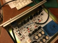
Ok I found the issue, I just noticed a hard to see x10 switch on the CRO leads, I must have knocked one to x10 rather that x1, I guess what threw me off was the dodgy looking square wave, Doh.
So now both channels look good and the square wave looks right now
My Beyer DT-1990pro's sound unbelievable on this thing, super happy


The FFT Graph looks good, 2nd 3rd and 4th harmonics @ 3 4 & 5Khz

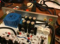
Just before I tidy up the wireing

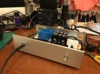
Front with power switch

Mark.
Ok I found the issue, I just noticed a hard to see x10 switch on the CRO leads, I must have knocked one to x10 rather that x1, I guess what threw me off was the dodgy looking square wave, Doh.
So now both channels look good and the square wave looks right now
My Beyer DT-1990pro's sound unbelievable on this thing, super happy
The FFT Graph looks good, 2nd 3rd and 4th harmonics @ 3 4 & 5Khz
Just before I tidy up the wireing
Front with power switch
Mark.
Last edited:

Thanks, Wayne. I will add the cap.The cap to chassis just provides a RF ground. Not required if it is silent but won’t hurt.


- Home
- Amplifiers
- Pass Labs
- "WHAMMY" Pass DIY headphone amp guide