I wanted other people to post before I commented.
The lack of UL taps on the O/P trafos is a major PITA. If relatively simple circuitry is to be used, triode wired "finals" seem (IMO) best. Some loop NFB around the O/P trafo rates to be a good idea. Foregoing the loop NFB requires absolutely top notch "iron" and, given the history provided, we can reasonably assume the available O/P trafos are not stellar.
A Mullard style circuit using a 12BH7 section as the voltage amplifier and a 12AT7 as the LTP phase splitter should yield a satisfactory gain structure. Reasonably high gm small signal types (like those mentioned) provide some protection against slew limiting.
Protect the O/P trafo cores against saturation, due to a LARGE low freq. error correction signal, by rolling infrasonic noise off at the amp's I/Ps.
boywonder said:Planet10: I'm not sure I got your point.......the design pairs good with these or doesn't have enough damping for these?....
Many/most of those like amplifiers with low damping/high output impedance.
dave
Because they sound GREAT!
Hi Allen,
Should read: Because you think they sound great
") !
!I think single triodes sound BETTER!
About your amps odd order distortion the odd orders would be even lower using single triodes. 2nd harmonic maybe would be a tad higher, though.
The cathode circuit in your output stage seems interesting, will dig deeper into it....
About designing correct, it goes for all circuit doesn´t it
.I simmed your circuit at 10mA through the CCS, maybe you go higher?
About other recommedations I would say: Stay away from Mullard inspired designs with their limited PI output swing and high NFB! As Allen says use high Gm tubes at higher current. So skip the 12-family. Go for 6DJ8, 6C45, 6H30, 5842 etc.
Seems a bit of a sweeping statement - you sound like Morgan Jones, who didn't have much good to say for the Mullard 5-20 in his Valve Amplifiers.Stay away from Mullard inspired designs with their limited PI output swing and high NFB!
I think it all depends on how you implement the topology. Mullard had an agenda with the 5-20, which was to promote their audio tubes, the EF86, ECC83 and EL34. Not only is ECC83 (12AX7) unsuitable as a phase inverter/driver, it also gives far too much gain together with the EF86. Even with the high levels of NFB used, at about 125mV RMS the amp was still ridiculously sensitive for today's signal sources.
However, there is no need to use Mullard's selection of tubes. If you implement the topology using more suitable tube types (lower gain and lower internal impedance) and reduce the level of NFB to suit, then the Mullard design is a good basis on which to build.
An improvement well worth considering to provide better balance, IMHO, is a CCS tail for the phase inverter.
Another improvement is to add a CF (or SF) pair after the phase inverter and before the OP tubes, to act as direct coupled drivers. At the same time, a change shoulld be made from cathode bias to fixed bias. This will avoid the danger of blocking distortion on transients and will also remove any influence that the changing input impedance of the Class AB OP stage may have on the phase inverter, which Morgan Jones says is sensitive to such things.
These improvements can be added later. You can start off with a relatively simple Mullard-based design, then proceed from there to improve the design as and when it suits you to do so.
Seems a bit of a sweeping statement
Nevertheless you agree and clarify exactly what is so wrong with it
!A CCS with negative supply would fix the swing. With two triode-strapped E280F you could skip the input tube and still adapt some small amount of NFB.
I have the Mullard book and love it! Specially the part before the 5-20 where they deal with UL and triode-strapping. They choose the wrong alternative though.........
But if you redesign it as you propose it is not a 5-20.
I see this as a bit of a quandary. On the one hand, the defects of a poor OPT will be heard without loop NFB, as Eli suggests. On the other hand, a poor OPT can cause problems with loop NFB. The conclusion I reached is that you need a good OPT whatever you're trying to do.Foregoing the loop NFB requires absolutely top notch "iron"
smbrown said:Eli, you said, "Foregoing the loop NFB requires absolutely top notch "iron" " Can you elaborate on why? Are you thinking that the low end response of the transformer might be poor and NFB would help flatten the frequency response?
A lot of the less costly "iron" available exhibits unacceptable behavior at both freq. extremes. Loop NFB in combination with other measures deals with the matter.
As long as bass extension is "flat" to below 30 Hz., things are OK. That gets you below the deepest note a double bass can produce. Rolling infrasonic noise off at the amp's I/Ps protects against core saturation from an excessive LF error correction signal. Of course, reasonably decent magnetic headroom must be available. When "El Cheapo" was designed, we called for Fender Deluxe guitar amp replacement O/P trafos and restricted ourselves to the "6" WPC triode mode yields.
At the HF end, slew limiting due to a large error correction signal is the enemy. High gm small signal types are resistant to slew limiting and selecting them is rather obvious. However, inductively peaking the small signal HF gain reduces the net error observed at the speaker terminals. A smaller HF error there implies a lower level error correction signal.
Eli & Planet 10, thanks for the response. In my case I'm playing with a PP KT66 that recycles iron from a Heathkit A-9c amp. I gutted most of it, changed the 12AU7 which has one stage as a voltage amp and the other as a split load phase inverter to a 6SN7. I changed KT66 from pentode to triode mode and eliminated NFB loop. To me, it sounds great. Measures flat to 15hz, and up to about 15khz before any decrease in output, down just a bit at 20khz. However, in looking at square waves I see a pronounced leading edge over shoot, not sure why. If I take a closer look w/scope the leading edge looks like a small ringing at about 200khz. I'm not sure if I should pay any attention, or if there are measures I can take to solve without negative impact on the sound. Any thoughts? I did try putting in a small amount of NFB (no comp cap) to see if any change, but none that I see.
revintage said:
Sensitivity is on the low side but I suppose you have preamp? If not, it could easily be constructed using a single 6H30 together with two Lundahl LL1544A.
This sounds intriguing. Is the 1544 at the input? I thought it was easily saturated at line levels.
The 1544A in will manage to deliver 2Vrms out when connected 4:1.
I use it in a small preamp/iPod-dock I built for my wife using 6H30 and it measures and plays great.
http://www.diyaudio.com/forums/showthread.php?s=&threadid=131511&highlight=
analog_sa, I can send you the final schematic if you are interested.
In another thread I recommended LL1676 as an better option but got crititized for recommending too expensive stuff.
If wanting to go all symmetric inside a "Simple EL34 Push Pull Design" the 1544A would be a really good choice at the input with the primary unbalanced, 4:2+2. If needing more gain the 1550(also amorphous)could be used 4:4+4(=1:1+1).
Off course there are cheaper but good transformers out there but I would go for the Swedish stuff!
I use it in a small preamp/iPod-dock I built for my wife using 6H30 and it measures and plays great.
http://www.diyaudio.com/forums/showthread.php?s=&threadid=131511&highlight=
analog_sa, I can send you the final schematic if you are interested.
In another thread I recommended LL1676 as an better option but got crititized for recommending too expensive stuff
.If wanting to go all symmetric inside a "Simple EL34 Push Pull Design" the 1544A would be a really good choice at the input with the primary unbalanced, 4:2+2. If needing more gain the 1550(also amorphous)could be used 4:4+4(=1:1+1).
Off course there are cheaper but good transformers out there but I would go for the Swedish stuff!
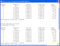
Allens output stage looked interesting so I simmed it side by side with Eriks conventional with a single 235ohm to ground.
Must say I am puzzled as Eriks has almost half the THD of Allens whether simmed with Allens or Eriks driver!
Both of course with the 3rd overtone dominating.
Did the sims with ca 4W/8ohm and the same OPT impedances.
As this is a static, theoretical sim, based on mathematical models of the tubes taken from their Ua/Ia-diagrams, it does not tell us anything about how they sound. Also, from what I have read, distortion sims aren´t always reliable.
The figures are from the ouput stages alone with balanced input.
Attachments
FWIW, the last cascode I built was a Tim de Paravicini oddball, a 6DJ8 cascode with very low current (0.5mA) and very large plate resistor (510k). Against all expectation, the distortion at 5.5V out was -58dB second, and third and higher were all below my measurement limit (-100dB).
jack firebrace said:Looking for a simple EL34 Push pull design. I have spent hours searching the net (and this forum) but not yet found anything suitable.
revintage said:SY, I think Jack asked for "Simple"
Jack,
maybe this thread can help
http://www.diyaudio.com/forums/showthread/t-93376.html
The last cascode I built was a 6DJ8 cascode with very low current (0.5mA) and very large plate resistor (510k). Against all expectation, the distortion at 5.5V out was -58dB second, and third and higher were all below my measurement limit (-100dB).
Its no wonder it works as with small currents Gm is still in the region of 1-2 mA/V. Its still got better Gm and linearity than a 12AX7. With a CF load you should have a gain of almost 60dB. So 5,5V out is then 5.5mV in. Assume you used it in some preamp.
How did it measure with 0,1V or 1V in? Or at a reasonable 25V out(power amp driver) with a 100k load.
I am not sure how to translate dB into % but isnt -58dB a rather high figure, just a little less than 0,2%?
I have been in cascode-land too, it was in the 70s-80s when cascodes where hyped. I earlier used a cascoded E88CC with Ra 100k in my RIAA but and it was OK.
Please show the schematic, it could be interesting to see if a sim correlates to reality.
I use 220k Ra together with a DC-coupled triode as CF in my guitaramps input stage. Gain is ca 55dB. Works very good.
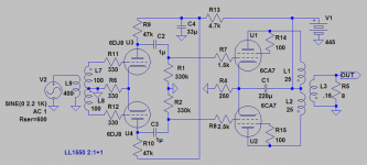
Searching for the simplest PP possible, transformer input must be the way to go!
If using a transformer-balanced out preamp the input transformer should be eliminated.
This adds a cost of up to £100 depending on transformers choosen. As this is a British request from the beginning, Sowter might be the choice.
If using a transformer-balanced out preamp the input transformer should be eliminated.
This adds a cost of up to £100 depending on transformers choosen. As this is a British request from the beginning, Sowter might be the choice.
Attachments
revintage said:Searching for the simplest PP possible, transformer input must be the way to go!
If using a transformer-balanced out preamp the input transformer should be eliminated.
are not input transformers even harder to get then the OPTs.
You can get input transformers in a day or two in the US, too.
0.2% second is not (IMO) a huge problem. Open loop, that's pretty darn good. The point was, though, that there wasn't any measurable odd order (your knock on cascodes).
but isnt -58dB a rather high figure, just a little less than 0,2%?
0.2% second is not (IMO) a huge problem. Open loop, that's pretty darn good. The point was, though, that there wasn't any measurable odd order (your knock on cascodes).
- Status
- This old topic is closed. If you want to reopen this topic, contact a moderator using the "Report Post" button.
- Home
- Amplifiers
- Tubes / Valves
- Wanted. Simple EL34 Push Pull Design