The only one I saw listed was in large volume and at high price. I like the look of these valves, they have all the right qualities, but I see little point in going down the route of designing around relatively rare valves. If this works out others might want to try the same and then a €6.00 Compactron makes far more sense.
Shoog
Shoog
I see 4 US offerings. One seller has many individual @ $13/per. Another has 2. One has 5 in one lot. (too much $) They come and go but I almost always see a few when I check. I have a dozen I've collected waiting for me to build a bunch of SE.
Can you get 4-8W /ch. from a compactron?
Can you get 4-8W /ch. from a compactron?
They must be US sellers who don't list for international sale. That is the problem with Compactrons as well - but someone has found a Spanish seller for the 6BN11 so thats no longer an issue for me.
Do I need to ? Spuds are for fun and if you haven't got the speakers to hear that fun then its not a game you can play. My main speakers sing nicely on 1watt so I can play.
Shoog
Do I need to ? Spuds are for fun and if you haven't got the speakers to hear that fun then its not a game you can play. My main speakers sing nicely on 1watt so I can play.
Shoog
What about the 6U10?
Use two lo mu sections (like 12au7) as a self split PP output, and the hi mu (like 12ax7) as a pre-stage. Should allow for some significant nfb as well to smooth things out. The whole thing can be powered by a cheapie 220~240V isolation transformer. You should end up with ~1W of pretty clean output and low parts count.
Use two lo mu sections (like 12au7) as a self split PP output, and the hi mu (like 12ax7) as a pre-stage. Should allow for some significant nfb as well to smooth things out. The whole thing can be powered by a cheapie 220~240V isolation transformer. You should end up with ~1W of pretty clean output and low parts count.

Found this interesting table of data:
http://www.jogis-roehrenbude.de/Leserbriefe/Gerphis-LV3N-Amp/6BN11-Triode.pdf
Suggest that I should be able to push 20mA through one of these at 150V and -1V on g1.
There cheap as chips so I can afford to run them hard. I would also suspect that the datasheet has conservative ratings.
Shoog
http://www.jogis-roehrenbude.de/Leserbriefe/Gerphis-LV3N-Amp/6BN11-Triode.pdf
Suggest that I should be able to push 20mA through one of these at 150V and -1V on g1.
There cheap as chips so I can afford to run them hard. I would also suspect that the datasheet has conservative ratings.
Shoog
Last edited:
Already ))What about the 6U10?
. .. Should allow for some significant nfb as well to smooth things out. The whole thing can be powered by a cheapie 220~240V isolation transformer. You should end up with ~1W of pretty clean output and low parts count.
View attachment 630000
- The gain of such is just enough, forget about "significant nfb";
- If you want to run the output stage at the max of acceptable 10 mA the B+ is limited to +210V. The mains trafo in fact has to be carefully picked;
- If you rise the B+ then you have to make the OPT like 100K p-p which is wishful thinking;
- 1 WPC is 200% optimistic;
All above comes from practical experience of the completed project.
Ok so my estimates were a little over ambitious, but I thought yours must underachieving. What about this schemo? I know it's not from a practical project, but based on proven principles. It should pump out just over 0.8 Wpc at just under 0.5% thd with sensible input sensitivity.
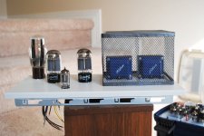
I like the glow of your 6U10s though

Attachments
OK, you asked for it, let's clean out the BS:
- Without the grid stoppers it is prone to oscillate;
- With grid leak greater 300K it is prone to oscillate;
- With 300K grid leaks the 220K plate load makes nonsense;
- I emphasize if you have difficulties to get it: the 6U10's AU7-parts have the common 4Wa max dissipated vs 5.5Wa of the separate 12AU7 == 1.5Wa is a SIGNIFICANT difference here;
- Which limits the B+ to 205V MAXIMUM with max allowed 10mA and the 5-7V drop across the CCS (6V typically);
- If you run it at 12+ mA the tube noticeably wears out in A MONTH;
- The common cathode output stage is less efficient than the common CCS;
- The common CCS sounds better than self-inverter, just take my word on this;
- I laughed most at your 22K p-p OPT )) in my project I got BARELY acceptable sound quality with 40K p-p.
SHAX
It's a concept only. Add 1k CC at the grids and you're ready to go.OK, you asked for it, let's clean out the BS:
- Without the grid stoppers it is prone to oscillate;
The datasheet says 1M is good, that's what I used for my concept. If you're smarter than the datasheet, thx for letting the world know..- With grid leak greater 300K it is prone to oscillate;
What about cleaning out the BS???- With 300K grid leaks the 220K plate load makes nonsense;
This design runs at 2W Pa per 12U7 triode.- I emphasize if you have difficulties to get it: the 6U10's AU7-parts have the common 4Wa max dissipated vs 5.5Wa of the separate 12AU7 == 1.5Wa is a SIGNIFICANT difference here;
That's why it runs at about 8mA per finals triode.- Which limits the B+ to 205V MAXIMUM with max allowed 10mA and the 5-7V drop across the CCS (6V typically);
- If you run it at 12+ mA the tube noticeably wears out in A MONTH;
Common CCS is a kind of self-inverter. What are you talking 'bout? Also, I made no claims on sound quality. Too subjective.- The common cathode output stage is less efficient than the common CCS;
- The common CCS sounds better than self-inverter, just take my word on this;
It's what you get with a Hammond 125A as a COTS part. Please show us your schemo, so we know what cha actually talkin bout.- I laughed most at your 22K p-p OPT )) in my project I got BARELY acceptable sound quality with 40K p-p.
So we are down to 12AU7 tubes now? 
Any tube with a 22K or 40K OT is going to sound bad. Not the tube's fault.
Minimum: 815 tube, 10W + 10W, not real common now.
I suggest measuring the volume of the 815 tube and just set that as the total tube volume limit. Then get some sub-mini and mini tubes to fill up that space.
"Fake" 42KN6 (doublet) looking better all the time. 12HE7 has 1/2 of 42KN6 (doublet) in it, so use two of them. You'll only be using 1/2 of the 12HE7, so thats a fair trade. 1/2 + 1/2 = 1
All the 12HE7 pentode pins, 8 thru 12, are even on one side, so a laser --could-- cut these tubes in half length-wise. Then laser weld two pentode sections back together!! An optical illusion with mirrors and two tubes would be easier though.
Any tube with a 22K or 40K OT is going to sound bad. Not the tube's fault.
Minimum: 815 tube, 10W + 10W, not real common now.
I suggest measuring the volume of the 815 tube and just set that as the total tube volume limit. Then get some sub-mini and mini tubes to fill up that space.
"Fake" 42KN6 (doublet) looking better all the time. 12HE7 has 1/2 of 42KN6 (doublet) in it, so use two of them. You'll only be using 1/2 of the 12HE7, so thats a fair trade. 1/2 + 1/2 = 1
All the 12HE7 pentode pins, 8 thru 12, are even on one side, so a laser --could-- cut these tubes in half length-wise. Then laser weld two pentode sections back together!!
An optical illusion with mirrors and two tubes would be easier though.
Last edited:
I am glad to see that people are thinking about the issues concerning a spud choice.
For me the analysis boils down to a few important choices.
1- valve has to have high transconductance, I would place this as a minimum of 10mA/v, this fairly much counts out most if not all of the available triodes. Not even the ECC99 can offer this. Fairly much all of the likely candidates are pentodes - which can be triode strapped.
2- has to offer medium to high gain. Why ? because it would be great to have some gain to burn up in some feedback to lower the pentodes high rp without having to resort to massive transformer impedences.
4- input transformers can help out a lot be offering an easy path to apply feedback (Schade style) and the possibility of a small step up. Input chokes are even better because they tend to have lower capacitance.
5- pentode has to have low input capacitance otherwise we cannot use any step up transformer without losing significant bandwidth.
An extensive trawl of just about all the dual pentodes/tetrodes points to the 6BN11 been just about the only candidate for the application of a single bulb PP spud. There are a few of the dual tetrodes but most of them have marginal gm for the task.
So as far as I am concerned its got to be pentodes all the way. Even using a three triode compactron cannot compensate for the multiple advantages which a high gain pentode offers.
An interesting possibility that presents itself is, if there could be found a power valve with similar components to the ECF80 in preamp role, we could make a nice triode - antitriode push pull pair. What would be needed would be a pentode and a triode in the same bottle with similar plate current capabilities.
Shoog
If we aim for the last option, a triode antitiode pair then we can consider:
6BH11 Pentode plate current- 12.5 gm- 7.5mA/V dissipation- 2.5W
Triodes Plate current- 13mA gm- 8.5mA/V mu- 46 dissipation- 2.5W.
This offers the option of either putting the pentode up front to generate massive gain for feedback, or a respectable triode driver of a triode-antitriode output.
Shoog
6BH11 Pentode plate current- 12.5 gm- 7.5mA/V dissipation- 2.5W
Triodes Plate current- 13mA gm- 8.5mA/V mu- 46 dissipation- 2.5W.
This offers the option of either putting the pentode up front to generate massive gain for feedback, or a respectable triode driver of a triode-antitriode output.
Shoog
I have some OEP input transformers which I am salvaging from my old 6080 DC7 MkIII amp. Don't know the specific model number off the top of my head.
Would love to go with something more exotic but this is just a cheap amp. Might try configuring it as a input choke by stringing the primary and secondaries in series.
Shoog
Would love to go with something more exotic but this is just a cheap amp. Might try configuring it as a input choke by stringing the primary and secondaries in series.
Shoog
An interesting possibility that presents itself is, if there could be found a power valve with similar components to the ECF80 in preamp role, we could make a nice triode - antitriode push pull pair. What would be needed would be a pentode and a triode in the same bottle with similar plate current capabilities.
Shoog
6F12P / 6Ф12П not really a power tube but:
triode: Pa=3.5W / gm=19 / mu=100 / Imax=22mA
pento: Pa=5W / gm=19 / mu(trioded)=100 / Imax=22mA
heater: 6.3V / 0.33A (hard to believe for a 3.5+5+0.4=8.9W combo)
diverse untested maybe incomplete spice models + datasheet in zip
Attachments
Last edited:
- Status
- This old topic is closed. If you want to reopen this topic, contact a moderator using the "Report Post" button.
- Home
- Amplifiers
- Tubes / Valves
- Want to build a PP spud.