Positive Feedback Article
The Positive Feedback article is very interesting.
I have seen it before and will receive a copy from a friend in France.
The article describes removing the feedback and output capacitor, has a LM317/LM337 based powersupply all by ...John Curl.
Also improvements for the RIAA (phono) amplifier are described.
Don't expect feedback from "Positive Feedback" they <B>NEVER</B> answered my e-mail!
Ren Hoek, please be nice! I don't think leiade is particulary annoying or tiresome.
leiade, I can't do everything for you but please sketch some ideas and then we will (nicely) give you comments. It's easier to know how you are thinking if we see some circuits from you. These rather simple circuits are not impossible to make with ratsnest or Vero-board.
The best you can do is look around and see all these millions of circuits. Check application notes, check also circuits in integrated opamps. If you can't "invent" see how others have done and don't belive everything you hear!
It's easier to know how you are thinking if we see some circuits from you.
He said he want's a JC-2 stage with Hitachi mosfet followers I believe. That's eight transistors. Is that too extreme for you to throw something together for the poor guy?
http://marklev.com/marklev/JC2/jc2schematics.jpg
"The best you can do is look around and see all these millions of circuits."
Oh that will help I'm sure. How many here have seen a million circuits? Can you please offer some real advice and not sweeping generalities PLEASE?
Ren
I don't know if leiade will use the phono amp as his buffer (no harm in that) or the other circuit.
Anyway if you want a MOSFET buffer, connect the sources to form the output. Maybe you have to insert source resistors in order to get better stability (temperature or oscillations). The gates can be connected to each source of the JFET's. You must change the source resitors of the JFET's so the voltage between the MOSFET gate will be 5-7 Volts. Also I think +-13 volts are a little bit too low. You will automaticly loose 3-5 volts top voltage because of the MOSFET's.
If the MOSFET's works allright without gate resistors, that OK, if not add 47-330 ohms but beware of that you will make the output stage slower and therefore get problems with the feedback.
Positive Feedback Article
Great I'm very interested in what's going on regarding the JC-2 wich seems to be on the track again.
If I remember things right there was an drawing error in the original JC-2 published in TAA is that error fixed or... I will search for a corrected scheme that a guy in Gothenburg Sweden has done in the beginning of 80's.
JC-2 output devices
peranders, I will use the line amp part of the JC-2 with very little gain about 5x may be resonable or... I can see a solution in all the links that I have collect i have already printed about on package of paper.
If it is better to use bipolar transistors I will go for that it's Ok! I have too little knowledge too judge what is the best I ask you peranders, I will not ask WJ or JC.
Again I will try to run some designs in my multisim and soon I will show my drawing for a judgement "the judgement day will come".
I apologize if I has been ironical it is hard to chat, sometimes it will go too fast with the questions and answers to participants.
Re: JC-2 output devices
BJT's, JFET's and MOSFET's have it's pros and cons. In small signal stages (not power amps) I would say I doesn't matter if you choose BJT's or MOSFET's. Choose the type you like and/or is possible to buy. Just for the fun of it I have designed a MOSFET headphone amp.
No problem at all! I think you are just "vetgirig" and that no harm in that. It costs you nothing to ask, noone will laugh at you.
Ren Hoek, please.....!
leiade said:If it is better to use bipolar transistors I will go for that it's Ok! I have too little knowledge too judge what is the best I ask you peranders, I will not ask WJ or JC.
BJT's, JFET's and MOSFET's have it's pros and cons. In small signal stages (not power amps) I would say I doesn't matter if you choose BJT's or MOSFET's. Choose the type you like and/or is possible to buy. Just for the fun of it I have designed a MOSFET headphone amp.
leiade said:I apologize if I has been ironical it is hard to chat,...
No problem at all! I think you are just "vetgirig" and that no harm in that. It costs you nothing to ask, noone will laugh at you.
Ren Hoek, please.....!
I have too little knowledge too judge what is the best I ask you peranders
Hey Man
What makes you think he has enough knowledge to help.
Go to:
http://www.borbelyaudio.com/dc102.pdf
He shows the bias network, gate resistors, source resistor (dived R40 by two and take out the output at the junction of these two resistors) and circuit design to drive the mosfet followers from BJT collectors. This will save you from having to look at the other 999.999 other circuits suggested by Peranders.
Get a clue
Ren
But but
But but...what shall I do with all my papers with application tip, turn them up side down and put them back into the printer?
Ok I will try your tip and I will also try about 25 tip that I have found on the web the best tip from the big paper tower that lies on my desk.
But but...what shall I do with all my papers with application tip, turn them up side down and put them back into the printer?
Ok I will try your tip and I will also try about 25 tip that I have found on the web the best tip from the big paper tower that lies on my desk.
Re: I have too little knowledge too judge what is the best I ask you peranders
Please, this isn't the way we should talk to each other. If you don't think my advice isn't worth anything, please keep it for yourself. I think some people do find advice can be something worth.
Ren Hoek said:Hey Man
What makes you think he has enough knowledge to help.
Please, this isn't the way we should talk to each other. If you don't think my advice isn't worth anything, please keep it for yourself. I think some people do find advice can be something worth.
JC-2 switch and connector
That was the circuit now to the switches and connectors.
A DIY from scratch switch would be very nice 48 or more reedrelays in some configuration.
Wich connector is most SOTA and wich is the most cost effective for high end audio.
Can this switch be used for both attenuator and source selector.
Wich connectors is SOTA and wich is the most cost effective. for high end audio.
The questions will be directed to this forum and any from poor to rich from not being a electronic design Guru to plain decent amateurs.
Re: JC-2 switch and connector
Now you are pushing it!
I typed switch AND selector in the search engine of this forum and got two pages full of threads!
Below is one of them:
http://www.diyaudio.com/forums/showthread.php?s=&threadid=3274&highlight=selector+AND+switch


I suggest doing a search too on the AudioAsylum, which has even a better searchengine.
Leiade,leiade said:That was the circuit now to the switches and connectors.
A DIY from scratch switch would be very nice 48 or more reedrelays in some configuration.
Wich connector is most SOTA and wich is the most cost effective for high end audio.
Can this switch be used for both attenuator and source selector.
Wich connectors is SOTA and wich is the most cost effective. for high end audio.
The questions will be directed to this forum and any from poor to rich from not being a electronic design Guru to plain decent amateurs.
Now you are pushing it!
I typed switch AND selector in the search engine of this forum and got two pages full of threads!
Below is one of them:
http://www.diyaudio.com/forums/showthread.php?s=&threadid=3274&highlight=selector+AND+switch
I suggest doing a search too on the AudioAsylum, which has even a better searchengine.

The SOTA buffer
Hi,
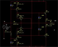
I have run a simple simulation of the WJ Buffer and it's just Ok is it possible to tune it to a SOTA buffer I have attached a copy of the image from multisim I hope it will be visible,
Anybody who is in the design game look at it and give me some reliable tip.
Hi,
I have run a simple simulation of the WJ Buffer and it's just Ok is it possible to tune it to a SOTA buffer I have attached a copy of the image from multisim I hope it will be visible,
Anybody who is in the design game look at it and give me some reliable tip.
Attachments
Punishment???
Helping G with his series connected regulators....
Artnyos are you a moderator?
Punishment, wrong attitude?artnyos said:I am shocked and dismayed at your attitude. You know that nobody will use the search engine. It would keep us from getting to answer the same questions 4 times a week. Shame on you.
For punishment you are to to go help G with his series connected three terminal regulator design.
Art.
Helping G with his series connected regulators....
Artnyos are you a moderator?
The SOTA buffer
I have changed some resistors and transistors same results low distorsion I even changed the LED one or more between the bases of the output devices but no same results low distorsion.
I suspect it is something " voodoo" in this design something must be wrong or maybe it's the ultimate amplifier I will run it on my breadboard and do som serious measurements with my HP 3580A I will even run my PC spectrum analyzer to se if it is obscure hidden illnes into it.
- Status
- This old topic is closed. If you want to reopen this topic, contact a moderator using the "Report Post" button.
- Home
- Amplifiers
- Solid State
- Walt Jung Class A preamp