If you are using a toroid transformer, just take some fine wire and make a few turns around the transformer and measure - enough for say 5V. Assuming 2V for the LED, that leaves 3V. Put a resistor in series (3/R) to limit the current to 5-20mA, depending on how bright you want.
Sheldon
I'd also toss a rectifier diode in series (or reversed, in shunt, your choice) with the LED. Some LEDS will fizzle out with a few volts in reverse across them.
Those capacitor banks are considered 'required' for the SMPS Bertrand is using (I have two of those myself). AP2 (Roberto) was quite explicit is saying to be sure to use them and they are supplied with the units.
Thank you..
Sooo does it make that SMPS sound better ??
Just seems as an Odd mix of Linear and Switching designs.
Last edited:
Better? I'd say that depends on which attribute you are talking about.
I think I will use the ones I bought and then go back to using good 'ol linear bulk supplies. Between failures and warranty return expenses much of the value and appeal disappears. I bought three different brands and had poor experiences with two.
I personally don't believe any PSU actually doing what it was chosen / designed to do impacts the sound. If the performance of the PSU does impact the performance of the amplifier to the point of audibility then it isn't supporting what is being demanded of it and should be considered either faulty or incorrectly conceived in the first place.
I put no stock in audiophoolery. I worked on an AV repair bench for a number of years and have seen and heard lots of nonsense in the field. I've even tried some of it in the name of 'science'. I sometimes damn near fall out of my chair at some of the stuff I read, here and elsewhere. A good design, well implemented will sound good, period.
Don't sweat the small stuff. So long as the power supply is adequate you should enjoy those little amps.
Yess keep looking at the forest not the trees.. thanks for the encouragement.
Recently /experimentally replaced my twin Arcam d290 amp setup on my Tannoy GRF's with a 'Lark' rebuild of my old unloved Dynaco st120 with Updatemydynaco.com Lm3886 refit kits (all).
Absolutely stunning differences; Deep solid hard hitting Bass, Exquisite treble and a Soundstage I can literally walk around in. Completely superior to the Arcams. Epiphany is an apt descriptor
Really annoyed at myself for the several thousand $ paid for the clearly worthless Arcams.
No idea If your/lc's VSSA will improve Sounds further over the lm3886 gizmo.. Hopefully so")
But as you say, the proof is in the hearing
Recently /experimentally replaced my twin Arcam d290 amp setup on my Tannoy GRF's with a 'Lark' rebuild of my old unloved Dynaco st120 with Updatemydynaco.com Lm3886 refit kits (all).
Absolutely stunning differences; Deep solid hard hitting Bass, Exquisite treble and a Soundstage I can literally walk around in. Completely superior to the Arcams. Epiphany is an apt descriptor
Really annoyed at myself for the several thousand $ paid for the clearly worthless Arcams.
No idea If your/lc's VSSA will improve Sounds further over the lm3886 gizmo.. Hopefully so
But as you say, the proof is in the hearing
OK Been busy(ish) Now have two boxes with SMPS fitted Both work Or at least there is 26.5 V on each rail ..both SMPS's read equally.. surprisingly given their humble origins.
15 v on secondary SMPS output rails
VSSA boards are on their heat sinks.. All ready to go.
I did read /print pge 10 Post 91
As My skills are only/just in Soldering pencil use.
Releasing Smoke is consequently a genuine concern.
Just follow the instructions ? I only have the Ammeter function on my Cheapo multimeter, it's claimed 10a is enough?
DC is measured at speaker output terminals ?
No issues running amp modules sans speaker loads?
All Hand holding info.. genuinely appreciated
Yes, follow those guidelines for set-up. It should be pretty straight forward. If your multimeter has a lower setting like 2A or even lower that will be more precise than the rough-n-ready 10A range. DC (offset) is measured at the amplifier output without a load. You will hook up a speaker or test load after all is shown to be running properly.
Since you are using an SMPS you don't have any real facility to limit your supply current. You may want to use a pair of 10R resistors in series with the +/-V lines to provide some limit in the event of a fault.
Since you are using an SMPS you don't have any real facility to limit your supply current. You may want to use a pair of 10R resistors in series with the +/-V lines to provide some limit in the event of a fault.
Thank you.
Just set the multi turn Resistors. Those really are 'multi turn'.
Will fit 10R 's then.
If the DC offset is under control .. what's the constant reference to Speaker protection circuits? Shorts ? Amp self destruction events ?
Do I need such ? Not today's concern though.
I fit my SMPS boxes with a lighted on off switch. Led is 2 v tho.
Suppose I can use the 15v rails or portion of. But what resistance would reduce it to 2v (Said I was a Newbie
We have flame And smoke
Added 11 ohm resistors betwixt + And - power input spades and their power supply wires as suggested.
Pretty well instant smoke then Flames.
Resistors burnt to a crisp.
No other damage evident.
Clearly I've bungled 'something" Sighhh. No Idea what though.
I did ..triple.. check the board stuffings. Months ago though
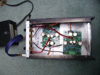
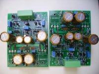
Attached photos for study... in case I've done something Obvious ??
Added 11 ohm resistors betwixt + And - power input spades and their power supply wires as suggested.
Pretty well instant smoke then Flames.
Resistors burnt to a crisp.
No other damage evident.
Clearly I've bungled 'something" Sighhh. No Idea what though.
I did ..triple.. check the board stuffings. Months ago though
Attached photos for study... in case I've done something Obvious ??
Attachments
Good question.. So I just now checked No shorts to the chassis On all 4 transistors on the board (s) I just powered and the as yet unpowered/tested one.
Was worried that I may have bits of wire /solder touching the heat sink metal.
Doesn't seem so ..so far.
Flamed resistors were 1/2 watters.. If that's significant ?
DO have a short/continuity between + spade - spade and Gnd spade (or any combination... on both PCBs ...tested one and not yet tested one.
Seems as possibly intermittent ..transistors working?? no idea
Frightening? or not??
Last edited:
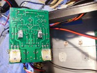
I can't see how you have the transistors mounted to the heatsink. I looks like the outputs and VAS transistors are mounted through the board. How did you get them all 4 tight to the heatsink when they are different thicknesses?
If you have a short from V+ or V- to ground it will obviously instantly burn any fuse/resistor that is in the path. You have got to find out where the short is. Can you give us a clear picture of the bottom of the board?
If you have a short from V+ or V- to ground it will obviously instantly burn any fuse/resistor that is in the path. You have got to find out where the short is. Can you give us a clear picture of the bottom of the board?
Aaaaahh. And here I thought I had Bungled the install of those wee plastic transistors by Not mounting them to a heatsink surface... Prior.. to soldering
Too late in realising Why those PCB holes were so large.
Seems I'm Not the only one then
I cut square bits of 1/16" thick Copper sheet 'spacers' (with screw holes) and with White goop on both sides,
inserted them betwixt Transistor and Metal case/heatsink.
I just checked the transistor prongs on the PCB for continuity with the heasksink.. Thinking along your same thought lines.
But No shorts. Will revisit it though.
Try to do a diode test on all the BJT's. + lead to the base leg of all N-channel transistors and the - lead to each of the other two legs. For the P-channel use the - lead to the base leg. You should see between .4v-.7v. Q1, Q5 and Q6 are N-channel and Q2, Q3 and Q4 are P-channel.
Try to get us a picture of the bottom of the board.
Try to get us a picture of the bottom of the board.
OK.. photo attached;
Slight soldering traces bungle .. I had initially gotten the wrong part # bit in the wrong place bit messy admittedly but it all meters as OK despite appearances.
Other board has no such weirdness.. mercifully.
No apparent evidence of dangly solder wires/bits even getting close/shorting to the Heatsink metal.
Did have to check though as you raised a valid point ..that was in the back of My mind as well.. to be honest
Frankly, I haven't a clue as to what a Diode test is.
But it does seem that to do what you describe...Power needs be applied.
Do I do this between the the onset of flames Or smoke ?
Yessss I too was worried about bungled fitment of the Black Box transistors .
As I ..had... gotten them wrong on first install, albeit months ago.
But I Did correct them..back then. Sreened numbers match the part # Or So I thought? [ OK just bent them over and Looked ...part # ARE correct}
Also had 'Some confusion' as to which direction the Smaller transistors faced in relation to the Heatsink. You gave an answer and I followed it.
Could it Still be wrong??
Not Whining here.... but there Was a lot of ambiguity re the assembly. Clearly, it's surfaced.
Slight soldering traces bungle .. I had initially gotten the wrong part # bit in the wrong place
bit messy admittedly but it all meters as OK despite appearances.Other board has no such weirdness.. mercifully.
No apparent evidence of dangly solder wires/bits even getting close/shorting to the Heatsink metal.
Did have to check though as you raised a valid point ..that was in the back of My mind as well.. to be honest
Frankly, I haven't a clue as to what a Diode test is.
But it does seem that to do what you describe...Power needs be applied.
Do I do this between the the onset of flames Or smoke ?
Yessss I too was worried about bungled fitment of the Black Box transistors .
As I ..had... gotten them wrong on first install, albeit months ago.
But I Did correct them..back then. Sreened numbers match the part # Or So I thought? [ OK just bent them over and Looked ...part # ARE correct}
Also had 'Some confusion' as to which direction the Smaller transistors faced in relation to the Heatsink. You gave an answer and I followed it.
Could it Still be wrong??
Not Whining here.... but there Was a lot of ambiguity re the assembly. Clearly, it's surfaced.
Attachments
Last edited:
Q8? Think I found it it's Flat faces the Blue Resistor Box as per the screened image.
Hard to read it's number but it mimics the silkscreen id.
This is driving me Nutz.. I'm fairly OCD So I tend to careful.
But early onset Oldtimers' may play a role as well.
Overheat possibly?? I use a geriatric Weller Craftsman pencil of 25 watts.
Hard to read it's number but it mimics the silkscreen id.
This is driving me Nutz.. I'm fairly OCD
So I tend to careful.But early onset Oldtimers' may play a role as well.
Overheat possibly?? I use a geriatric Weller Craftsman pencil of 25 watts.
Last edited:
What kind of meter do you have? It may or may not have a diode test feature but if it does it would go a long way toward discovering a problem. I don't see any issues with the bottom of the board. While you have it disconnected from the heatsink do one more continuity check just for kicks. While you're at it, do a continuity test on each of the transistors to see if any are shorted.
A couple of inexpensive 'circuit test' brand meters, one is auto-ranging.
I believe it has a diode test.
Soo transistors have 3 legs.. Which legs do I test ? What's a Good reading and what isn't?
Other board is as yet untested (so less likelyhood of it having incurred test induced damage. ?) Should I carefully compare it to the tested one? Surely they Both can't be Bungled?? Can they?
- Status
- This old topic is closed. If you want to reopen this topic, contact a moderator using the "Report Post" button.
- Home
- Amplifiers
- Solid State
- VSSA Through-Hole Version by Jason