Well, on normal 16/44.1 it sounds better. But on the higher res stuff 24/192 & some 24/96 it is has a little to much sizzle.( hard too explain ). Too sibilant maybe, to my ears anyway.I'm not ready to start a major swap out to figure it out at this point. Need to do some more comparison's. YMMV. ")
So far, each VSSA I have built needed a little time to burn in. Once they got some time on them the sibilance settled down. Now that I think about it, almost all of the amps I've built had a little too much sizzle when first powered up but settled down after some time. I usually let them run pretty hard for the first couple days.
Blessings, Terry
Blessings, Terry
I have never been a big practitioner of the burn-in procedure but I will soon have a point of comparison. My revision 'B' have been in service for some time now and my revision 'C' are almost ready, so I will try to A-B them as best I can to see if the newborn sounds any different than the burned-in one. They are the same circuit built using almost all the same parts as each other.
Just curious Terry, you mentioned possibly letting someone you know have one of the VSSA's. Given the choice which would you choose to keep for yourself and which would you give away? In just a few words, why?
Just curious Terry, you mentioned possibly letting someone you know have one of the VSSA's. Given the choice which would you choose to keep for yourself and which would you give away? In just a few words, why?
Hi Jason,
That's a good question. It wouldn't be the TO-3 version mainly since it has the old rusty looking outputs and home brew boards. Your new version isn't in a case yet so I guess it would have to be PMI's version. They all sound the same so that wouldn't be a consideration. I am short on power supplies right now and am trying to decide rather to buy more transformers or SMPS's. I have one more Cap multiplier so I may buy one more transformer to use with it but I am leaning toward going to SMPS for everything new. Your boards sound really, really good on the SMPS.
Blessings, Terry
No such thing. All are satisfying but some are better on some genres than others. Bang for the buck, my favorites right now are probably VSSA, SKA and DX Super A. I just built a FetZilla and it sounds really good but I haven't had enough time to really do good comparisons. The only one of those I wouldn't recommend is the Aleph-X. All of the others sound wonderful.
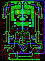
VSSA with integrated CM
This should be getting close to a workable version with an integrated CM to feed the IPS and VAS. I included some pads for wire links to either power the CM off the main supply or to leave it off to feed the CM with boosted rails.
I have not yet messed about with the CCSs, at least as yet. I noticed that it is also very easy the bias the front end just like the PeeCeeBee version via resistors. This allows for three options for builders, the originally intended 2Q CCS, the 1Q+LED CCS as first noted by Sheldon, and finally the PeeCeeBee style resistive bias.
By leaving off Q3, Q4, Q5, Q6, R11 and R12 and installing two 10K resistors, one from Q3's base pad to Q4's collector pad and the other from Q6's base pad to Q5's collector pad, and using 10K trimmers for VR1 and VR3 we can use the current boards as a PeeCeeBee for those who want the fewest active components possible. I'd still leave Q8 for biasing as opposed to a diode string, fully adjustable bias is too convenient to throw away, though possible too.
Any comments? Silk is not fully worked out yet, so don't hang me out on that just yet.
This should be getting close to a workable version with an integrated CM to feed the IPS and VAS. I included some pads for wire links to either power the CM off the main supply or to leave it off to feed the CM with boosted rails.
I have not yet messed about with the CCSs, at least as yet. I noticed that it is also very easy the bias the front end just like the PeeCeeBee version via resistors. This allows for three options for builders, the originally intended 2Q CCS, the 1Q+LED CCS as first noted by Sheldon, and finally the PeeCeeBee style resistive bias.
By leaving off Q3, Q4, Q5, Q6, R11 and R12 and installing two 10K resistors, one from Q3's base pad to Q4's collector pad and the other from Q6's base pad to Q5's collector pad, and using 10K trimmers for VR1 and VR3 we can use the current boards as a PeeCeeBee for those who want the fewest active components possible. I'd still leave Q8 for biasing as opposed to a diode string, fully adjustable bias is too convenient to throw away, though possible too.
Any comments? Silk is not fully worked out yet, so don't hang me out on that just yet
.Attachments
You are rockin' ... J.
Having options is nice ...but it could confuse some...
Your layout is cutting edge ... this simple CFA will most likely
be double digit PPM in normal use.
Some of your techniques were used on the "CFA-X"
OS
Thanks, OS. Again your comments are always welcome. I'm very humbled you used the phrase 'cutting edge' to describe my efforts
.I agree that too many options can be a bad thing and could confuse a newer builder - especially considering this design's simplicity is apt to attract a builder with less experience. I think I will try to curb my desire to make this 'universal' for a few reasons with avoidance of confusion being paramount.
I just thought I'd mention the resistive bias since it is another happy accident and requires no cutting or modification of the board at all. Neither the 1Q+LED CCS or the resistive bias techniques were considered during layout but fit perfectly as is.
In any event I will be a little while before being able to get this ready for production but will post some final images when I am ready to move forward.
Got mine all buttoned up. They're in a case with a pair of Symasyms. Power supply is a 500VA toroid with 20mF per side. Did a little testing on the scope and compared with the Symasym:
Square waves look good on both. The VSSA rolls off a little lower than the Sym, but that is due to the input filter. The Sym has 100pf across a 22k load resistor, as compared with 470p across 10k for the VSSA.
Played around with powering up the Sym and looking at the VSSA output, and visa/versa. If anything, the Sym is a little more influenced by the external load on the power supply, than the VSSA (taking into account gain - Sym is 32dB, VSSA is 27dB. In other words the VSSA PSRR is at least as good as the Sym. As I plan to use them for mid(sum) and high(VSSA) in a sensitive system, PSRR should not be an issue.
The VSSA does seem more sensitive to grounding. I can induce some overshoot and damped ringing on the VSSA by playing with the scope ground. I don't see the same with the Sym.
Next step is to listen in a few days.
Sheldon
I put up a few pictures in the group buy thread if anyone would like to see the Rev 'C' boards fully stuffed. I didn't want to upload the same ones twice and don't know if you can 'recycle' your attachments to show in a second thread or not.
http://www.diyaudio.com/forums/group-buys/251782-vssa-through-hole-version-jason-5.html#post3853273
Sounds like an interesting set-up you are going for Sheldon. Put up a pic or two if you are so inclined.
http://www.diyaudio.com/forums/group-buys/251782-vssa-through-hole-version-jason-5.html#post3853273
Sounds like an interesting set-up you are going for Sheldon. Put up a pic or two if you are so inclined.
OK, for those who need a little guidance with the BOM, or who don't feel comfortable choosing components, here is a Mouser specific BOM. It is not carved in stone, feel free to use whatever components that fit the board and your fancy, these are just my personal suggestions.
Note: The BOM doesn't list the Output MOSFETs since they aren't readily available from Mouser and I have been getting them from Tayda Electronics. Electrical connectors, stand-offs, mica / sil-pads are also not listed and are at the constructors discretion. I have made every reasonable effort to make this BOM accurate but please let me know of a serious omission or error and I will correct it and re-post or have a moderator replace the attachment if necessary.
I hope this helps anyone who might need or want it.
Attachments
Last edited:
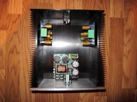
Funny how clean an install can be using an SMPS. Have you fired it up with the SMPS yet? I can't hear anything that would lead me to believe it isn't just as good as my trafo and cap multiplier. Less than half the weight and space.
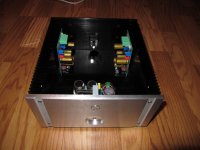
Beautiful case.
Blessings, Terry
You bet the install will be 'clean' with this SMPS in there. This thing is about the size of a 250VA toroidal transformer, never mind the rest of the supply. If it works as well as I hope it will I may never use a linear bulk supply again, except perhaps to recycle parts from old equipment.
I haven't tried it yet. I need to get some more mounting hardware, so it will have to wait until it can be properly mounted. My only debate is wether or not to centre the amplifiers on the heat sinks, which brings them in closer to the SMPS, or to leave extra physical room as pictured.
The case is quite nice. I'm planning on some kind of insert to block off the volume control mounting location. Perhaps a nice aluminum disc, raised and beveled with a nice 'VSSA' engraved into it. The piece I can machine in the garage and I likely have stock in the appropriate size too.
Nice work!You bet the install will be 'clean' with this SMPS in there. This thing is about the size of a 250VA toroidal transformer, never mind the rest of the supply. If it works as well as I hope it will I may never use a linear bulk supply again, except perhaps to recycle parts from old equipment.
I haven't tried it yet. I need to get some more mounting hardware, so it will have to wait until it can be properly mounted. My only debate is wether or not to centre the amplifiers on the heat sinks, which brings them in closer to the SMPS, or to leave extra physical room as pictured.
The case is quite nice. I'm planning on some kind of insert to block off the volume control mounting location. Perhaps a nice aluminum disc, raised and beveled with a nice 'VSSA' engraved into it. The piece I can machine in the garage and I likely have stock in the appropriate size too.
My opinion is,you MUST centre the amplifiers on the heat sinks.
The reason is that centre,is the only way for isothermal distribution.
Waiting for listening test with SMPS.
Transformers and capacitors are very expensive these days
Last edited:
- Status
- This old topic is closed. If you want to reopen this topic, contact a moderator using the "Report Post" button.
- Home
- Amplifiers
- Solid State
- VSSA Through-Hole Version by Jason