Hello iaxxaxxai,
Thank you for that link, I have bookmarked it. Did not know about this website.
I can get it shipped to some one in US and get to India, no issues with that. Awaiting LC's confirmation if we can use these caps.
Thanks
Silmics are too big(16mm) to fit properly. Max. that can fit in that position is 12,5mm in diameter. You can bend a current source transistors a little, but those 10uf MKT are also in the way. See post #318,#332. I have also trouble finding Nichicons FG 2200/6.3 and 1000/50 together so it means separate orders and shipping cost
 .
.GB Capacitors dimensions info
I am repeating the info posted in #978 just for clarification how big capacitors can be, not a mm bigger.
Yes, there will be 250 sets in this GB, so at this time there are still some 30 PCB sets available.
Capacitor dimensions for VSSA PCB:
- 10 uF/63 V, MKT, Vishay-Roederstein, 2 pcs
Lead Spacing: 15 mm
External Depth: 8.5 mm
External Height: 17.5 mm
External Width: 18 mm
- 2200 uF/6,3 V, FG, Nichicon, 2 pcs
Lead Spacing: 5 mm
External Diameter: 12,5 mm
External Height: 25 mm
- 1000 uF/50 V, FG, Nichicon, 4 pcs
Lead Spacing: 7,5 mm
External Diameter: 16 mm
External Height: 31,5 mm
Three preinstalled SMD trimmers will be permanently located on PCB, type 5 tourns, Bourns, for DC offset/VAS bias (2) and output bias (1) setting.
I will also add a Kapton insulator for TO-247 and two plastic spacers for TO-126.
Assembling and calibration will be straightforward and very simple.
Regards Andrej
I am repeating the info posted in #978 just for clarification how big capacitors can be, not a mm bigger.
Payment sent via Paypal
Hi LC,
Been waiting for your confirmation but sent you the funds last May 21st. Kindly advise.
Thanks,
WP
Hi LC,
Been waiting for your confirmation but sent you the funds last May 21st. Kindly advise.
Thanks,
WP
Hi GB members
73 out of 86 GB members already payed and confirmed VSSA orders. Thanks a lot.
13 GB members still on the move to pay and confirm. If someone from this remaining group intends to cancel the order please let me know soon, cause some new guys are waiting in the row to receive the offers.
Delivery note (without any price stated) and VSSA installation manual will be included inside the parcels shipped to each delivery address.
Invoices will be send separately to your e-mail addresses.
Tomorrow all pre assembled VSSA modules will finally be delivered to me.
Regards, Andrej

Hi LC,
I've check the Nichicon FG at Element14/Farnell(Singapore) but they don't have, do you have a list of preferred capacitors other than this particular Nichicon FG?
Also, found out that the 10uF/100V Vishay Roederstein capacitor is a lot cheaper(7X) than the 63V one. Too bad the dimension (width) is 8.5mm longer. The height and depth is only 1mm and 2mm larger though. I suppose there is no difference using this other than making it fit on the board.
Regards,
WP
Hi WP,
You will have a hard time to make the 10uF/100V Vishay Roederstein to fit as the lead spacing is 22.5mm. LC also used the following cap on one of his board: B32522C106K - EPCOS - CAPACITOR POLY FILM 10UF 63V 10 | element14 Singapore
For 2200uF, you can consider Rubycon ZL - 6.3ZL2200MEFC10X23 - RUBYCON - CAPACITOR, 2200UF, 6.3V | element14 Singapore or 10ZL2200MEFC12.5X20 - RUBYCON - CAPACITOR, 2200UF, 10V | element14 Singapore or
EEUFM0J222L - PANASONIC - CAPACITOR, RADIAL, 2200UF, 6.3V | element14 Singapore
According to Rubycon datasheet - Enabled high ripple current by a reduction of impedance at high frequency range.
OK, we have to stick to LC's recommendation as far as decoupling and feedback caps are concerned.
What about the power supply caps? What value of power supply caps should I use if I plan to use linear power supply? Is 3*4700uF, 63V per rail sufficient? I need to order this along with other caps. Any other suggestion regarding value and manufacturer is welcome.
What about the power supply caps? What value of power supply caps should I use if I plan to use linear power supply? Is 3*4700uF, 63V per rail sufficient? I need to order this along with other caps. Any other suggestion regarding value and manufacturer is welcome.
GB Info
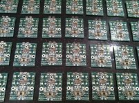
Hi GB members
First VSSA PCB batch arrived, all others before Wednesday, since I ordered the guys to clean up all PCBs more precisely.
The delivery formula will have "and" function between order date & payment date, I think this is most fair approach.
First ones expect PCBs next week.
Regards Lazy Cat
Attachments
For 2200uF, you can consider Rubycon ZL - 6.3ZL2200MEFC10X23 - RUBYCON - CAPACITOR, 2200UF, 6.3V | element14 Singapore or 10ZL2200MEFC12.5X20 - RUBYCON - CAPACITOR, 2200UF, 10V | element14 Singapore or
EEUFM0J222L - PANASONIC - CAPACITOR, RADIAL, 2200UF, 6.3V | element14 Singapore
According to Rubycon datasheet - Enabled high ripple current by a reduction of impedance at high frequency range.
I would personally avoid Rubycon ZL capacitors, no matter how data are good. If Nichicon FG are not obtainable, then I suggest Panasonic FC. FM are avoidable too. Here you have some interesting link: High End Audio - Electrolytic capacitors
baswamin: you got pm!
Nichicon PW-series, 50V/2200uf, if they fit the board....and my personal choise only
http://docs-europe.electrocomponents.com/webdocs/0ec9/0900766b80ec9186.pdf
http://docs-europe.electrocomponents.com/webdocs/0ec9/0900766b80ec9186.pdf
How about ELNA ROA Cerafine 2200uF / 6.3V, 16mmD x 25mmL, $2.10 Each.
looks like a perfect cap for this position.
Elna Electrolytic Capacitors ROA Series
looks like a perfect cap for this position.
Elna Electrolytic Capacitors ROA Series


There is no 15K on this board, that was an early version of the schematic.The 2200uF is for low voltage portion as the voltage is dropped by 15K ohm resistor.
The 15K was replaced by a CCS made up of a JFET and a resistor (shown in V1.4 of the schematic, post #300). The 2200 uFd cap in this version is 10V.
At some point, the value must have been reduced to 6.3V, and a trimmer added. The BOM in post 705 lists 2200 uFd 6.3V, 5mm lead spacing. It also has the p/n of the JFET, BF545B, which is rated at 30V maximum. The CCS current is supposed to be 2.4 mA.
So, if you want to substitute another 2200 uFd cap, you basically have to calculate back from those figures. Or just get what LC specified, in your own choice of color, of course. Gold is SO last fall...
Thanks PMI, correctly to the last detail.The 15K was replaced by a CCS made up of a JFET and a resistor (shown in V1.4 of the schematic, post #300). The 2200 uFd cap in this version is 10V. At some point, the value must have been reduced to 6.3V, and a trimmer added.
2200 uF was reduced to 6,3 V since there's 0,65 V DC present on this cap, meaning it is biased too and that is soooo goood. Why? Think for a second about small tiny signals, no crossover distortions hehehe. Actually many companies in high end do this, example is my Trio speakers, all Mundorfs are + 200 V DC biased for exactly the same reason. And there's also a story that ELCO V rating should be close to its DC potential, that was the reason I went down to 6,3 V.
It is all about the detail and sum of all details gives the whole performance picture.

I enjoy listening VSSA right now, Alison Krauss & Union Station on menu and I would really like you all to hear the same performance at your homes. Please follow my advices to the last detail explained in this thread, especially about SMPS, than you'll hear what I mean.

sad news... Philistines at the bank will not write a second mortgage to finance speakers...I enjoy listening VSSA right now, Alison Krauss & Union Station on menu and I would really like you all to hear the same performance at your homes...
Thanks PMI, correctly to the last detail.
2200 uF was reduced to 6,3 V since there's 0,65 V DC present on this cap, meaning it is biased too and that is soooo goood. Why? Think for a second about small tiny signals, no crossover distortions hehehe. Actually many companies in high end do this, example is my Trio speakers, all Mundorfs are + 200 V DC biased for exactly the same reason. And there's also a story that ELCO V rating should be close to its DC potential, that was the reason I went down to 6,3 V.
It is all about the detail and sum of all details gives the whole performance picture.
I enjoy listening VSSA right now, Alison Krauss & Union Station on menu and I would really like you all to hear the same performance at your homes. Please follow my advices to the last detail explained in this thread, especially about SMPS, than you'll hear what I mean.
It will be going toe to toe with TSSA and some Firstwatt stuff
sad news... Philistines at the bank will not write a second mortgage to finance speakers...
Ooo I'm sorry to hear that, I apologize to forget, what kind of speakers were canceled, please tell.
Maybe we all can help with an alternative choice.
- Home
- Vendor's Bazaar
- VSSA Lateral MosFet Amplifier