Two VSSA use 30 Watt of constant standy power. It comes from SMPS, So SMPS is loaded with 30 Watt + 10% efficiency, so 33 Watt of standby power without playing music. This is 33 Watt of RMS power.
In the Hypex datasheet it states that SMPS400 is 400 Watt music power and only 1/8th of music power is true RMS power. SMPS can deliver 400 Watt on short term, on the long term SMSP400 is capable only 50 Watt. Delivering more power will overheat the SMPS and posibly make it fail?!?
At least this is how I understand their datasheet.
Ok I read it differently.
Ok I read it differently.
Please look at chapter 6.4. http://www.hypex.nl/docs/SMPS400_datasheet.pdf
There are also power ratings, i believe they are for music power and not RMS.
UcD hypex amps are class D so they are high efficiency, therefore not imposing a big load on the smps. With VSSA and especially First One it is different.
No rush about it, VSSA v1.5 ready made modules PCB size 50 x 60 mm will be available in early 2015.Who can drow a pcb for this?
Alex ,do you hear?
Jason are you here?

Hypex unregulated SMPS makes amp's sound more relaxed and coherent especially in mid-high audio spectrum as proven in many listening tests here. One option would be to have stabilized PSU (stabilized cap multiplier) without regulation feedback, implemented in front of an amp's power input.I'm using a Conex electronic Smps500R to power both channel of my Vssa and is doing a good job. I donț know If sounds better or worse than Hypex.
")
That's good news but we are diy fanatics don't forget this.No rush about it, VSSA v1.5 ready made modules PCB size 50 x 60 mm will be available in early 2015.
Attachments

Last edited:
The SMPS500QRv2 from Connexelectronics though is unregulated Connexelectronic
do you think that would work better?
do you think that would work better?
Hi,
This is what Connexelectronic answered me when I inquire about this model;
''SMPS500QRv2 output voltage +-40 to 45V max. current which can be supplied continuously is about 3-3.5A on each rail installed on a proper ventilated enclosure and 2.5-3A in a sealed enclosure. the max current which can be supplied with music program is about 2.5 times higher.''
Power wise it looks OK, it's also unregulated so this probably helps but I haven't tried it.
Looks good.
BR,
Eric
Hi,
Just acquired 2 modified SMPS400A180 (as per LC recommendation) but I'd like to re-install the NTC to prevent inrush.
Does anyone know the value or model number of the NTC (R45 on PCB) so I can order a few.
TIA,
Eric
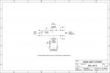
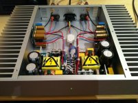
Picture one is schematic how LC did mod inrush current by a error free soft start circuit (orange RTL33L012 relay and black CL-90 NTC is just viewable in picture two behind green led in front panel), and zoom in on picture two to see DC sense protection wire from hot speaker output going back to Hypex connector pin.
Attachments
Soft start schematic is OK, thanks ByrttThis is great, thanks.
p.s. Looks like R1 (330 ohm) must be rated 1W.
There is a wire connected to J6, is this the DC error detection that will shutdown the SMPS400A180 ? Can this be used instead of a speaker protection module ?
Thanks and Best rgds,
Eric
R1 dissipates 33 mA * 10 V= 330 mW, so normal 0,5 or 1 W ressistor is OK.
SMPS400 has direct DC sense input, meaning direct +OUT wire connection to J6 pin 1 or 2 (page 9 in datasheet) and that is working fluently (100 kohm input impedance from J6 pin 1 or 2 to GND).
Yes, this arrangement can be used instead of speaker protection since in a case of DC error SMPS400 will shut down instantly.
L.C.

Attachments
Regarding SMPS400A180 have eye at J7 one of the 4 screws holding PCB is expected to have physical connection to the box.This is great, thanks.
.....
From post 3343 looks like you going with Jason or PMI modules and if you gets hum from finalized amp think it goes something like this: If using one SMPS for two amps it's ok to have 10 ohm ground lift at input, but if running one SMPS per amp module expect to short the 10 ohm ground lift at amp input to get it hum free.
Thanks a lot for the heads up regarding J7 and the 10 ohm at the input, I'll be using one supply per channel.
I have both the Jason's and PMI's so later I will try a pair of Connex 500Qr2 (unregulated) with the PMI amps to see the differences.
Thanks for the confirmation LC, much appreciated.
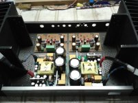
Pic of inside my VSSA (Hafler 220 enclosure)
BR,
Eric
I have both the Jason's and PMI's so later I will try a pair of Connex 500Qr2 (unregulated) with the PMI amps to see the differences.
Thanks for the confirmation LC, much appreciated.
Pic of inside my VSSA (Hafler 220 enclosure)
BR,
Eric
Attachments
..... I'll be using one supply per channel.....
Think it be a great amp.
Regarding J6 DC error remember to lift connection at first startup until amp is calibrated and no DC at output, else it can be difficult to get started PSU
.Another great advise, thanks
One more question : On my heatsinks I have room to install 2 x pairs of LatMos per channel therefore 4 Mosfet/amp, some people say that parrallel output device sounds worst some say it sounds better...how about VSSA, my load will be 4 ohm if that makes a difference.
Thanks again.
Eric
One more question : On my heatsinks I have room to install 2 x pairs of LatMos per channel therefore 4 Mosfet/amp, some people say that parrallel output device sounds worst some say it sounds better...how about VSSA, my load will be 4 ohm if that makes a difference.
Thanks again.
Eric
Think it be a great amp.
Regarding J6 DC error remember to lift connection at first startup until amp is calibrated and no DC at output, else it can be difficult to get started PSU
Hello Byrtt,
according to Hypex triggering voltage for DC error detection is +-12V, so I would think unless something is catastrophically wrong it would start just fine
Kind regards
Marko
Another great advise, thanks
One more question : On my heatsinks I have room to install 2 x pairs of LatMos per channel therefore 4 Mosfet/amp, some people say that parrallel output device sounds worst some say it sounds better...how about VSSA, my load will be 4 ohm if that makes a difference.
Thanks again.
Eric
What i've seen around here VSSA one pair output device configuration had no problems driving 4 ohm loads and feeding it by one SMPS per channel as in your setup think seems optimal, but If running dual pair maybe SMPS400A180 is too weak.
LC made a dual pair version in form of one pair which has double die, link is here and it looks great and have impressive specs but needs another beast of an PSU to feed it http://www.diyaudio.com/forums/vendors-bazaar/248996-first-one-mosfet-amplifier-module.html. If you later experience VSSA is too weak for your needs then a pair of First One modules could be the solution.
Hello Byrtt,
according to Hypex triggering voltage for DC error detection is +-12V, so I would think unless something is catastrophically wrong it would start just fine
Kind regards
Marko
Thanks okay 12V triggering then you right but didn't know the spec
....
Last edited:
- Home
- Vendor's Bazaar
- VSSA Lateral MosFet Amplifier