Anyone know where the adjustment procedure is? It looks like you'd have to tweak both sides for IPS current as well as DC offset.
Unsurprisingly, it's all in the manual LC published as a multipart pdf
")
Last edited:
Anyone point me to this? I'm slowly looking through this thread but I've another 1000 or so posts to go.Unsurprisingly, it's all in the manual LC published as a multipart pdf
Magic Smoke
Have a question.
i have Connex SMPS 500R and LC VSSA. Using for 1.5 days OK. Then i tried a Freq Sweep Tone from 5hz to 50Khz & before the tone could get out of 100Hz region my SMPS let out some Magic Smoke.
I powered off and while it still mostly works, it can't handle any high Load any more. Anyone have an idea Why this should have caused this problem? I have used this Freq Sweep tone before with no problems.
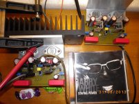
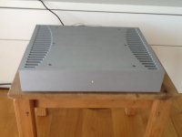
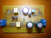
My finished VSSA
Hi guys!
I was able to finish my vssa amp last week and let it run for a full week.
I was able to hear previously finished product from LazyCat.
My amp at the moment differs to the from LazyCat mostly in choice of capacitors on vssa pcb. The power supply is identical.
We will do some sound comparisons in a few days and I will let you know.
Attachments
The last circuit schematic published is in post #300. There is a BOM in post #705, however the exact schematic and BOM of the modules for sale is not published, probably because that would put the final design in the public domain. You have to do your own detective work when you get yours...Anyone know where the final schematic is?
"Welcome to the Commercial Sector" ...
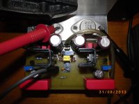
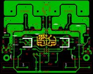
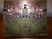
hi nikosokeyMy new version pcb
offset +- 3mv
2n5462 at 10 ma set to 2.4 ma
vas at 12.ma
exicon at 170 ma
Very nice amps you have there, did you end up with KSC/KSA VAS pole or is it BD devices.
Because you make so nice HD Pictures i am able to see you have a little copperwire around the input pole, no matter it is small signal, around those devices there must be audioband swinging electromagnetic field, so either use plastic/glue/or ground it.
It has just been discused in PeeCeeBee thread how it makes drifting the setup (see http://www.diyaudio.com/forums/solid-state/231662-peeceebee-112.html#post3616995).
Maybe also screw/nut/washer for VAS devices would benefit with nonmagnetic material brass/alu/stainless/(grounding) because of electromagnetic field.
Ricky
Last edited:
Thanks for this PMI.The last circuit schematic published is in post #300. There is a BOM in post #705, however the exact schematic and BOM of the modules for sale is not published, probably because that would put the final design in the public domain.
The BOM doesn't mention the FETs used for the IPS CCS.
Anyone who's built the kit tell us what FET is used there? Must be quite high Idss as the nominal value is 3k3 which means operating Vgs is -7.92V
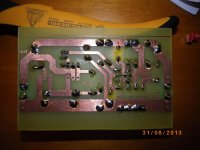
VSSA T03
Hi Ricky
Thanks for your kind words
Honestly I did not give much importance to the little copperwire around the input pole.
Next move i use glu for them .
I use bd 140 and bd 139 mached and on R =47Ω Ι measure 107mv
and 107mv to other res =2,27 ma to set 12ma the VAS
Square Wave at 100khz are perfect .
The amplifier with this the PCB has no hum noise at all .
When opening the amplifier with speakers 4Ω above the offset steering momentarily at 50mV and sits to 5mv no <<dooop>> at all.
i dont use KSC/KSA VAS pole because i dont have ksc3503 E ,ksc3503 D make peaks on square wave bigger offset <dooop> on power up BECAUSE have big diferent hfe .
Fantastic bass .treble . etc ..
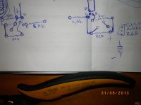
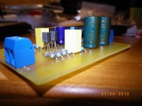
My new shunt reg for my B1 Buffer
Some sheet for CCS JFET P channel 2n6462 and trimmer to set 2.4 ma both sides + -
regards Nikos
Hi Ricky
Thanks for your kind words
Honestly I did not give much importance to the little copperwire around the input pole.
Next move i use glu for them .
I use bd 140 and bd 139 mached and on R =47Ω Ι measure 107mv
and 107mv to other res =2,27 ma to set 12ma the VAS
Square Wave at 100khz are perfect .
The amplifier with this the PCB has no hum noise at all .
When opening the amplifier with speakers 4Ω above the offset steering momentarily at 50mV and sits to 5mv no <<dooop>> at all.
i dont use KSC/KSA VAS pole because i dont have ksc3503 E ,ksc3503 D make peaks on square wave bigger offset <dooop> on power up BECAUSE have big diferent hfe .
Fantastic bass .treble . etc ..
My new shunt reg for my B1 Buffer
Some sheet for CCS JFET P channel 2n6462 and trimmer to set 2.4 ma both sides + -
regards Nikos
Attachments
Last edited:
Hi,
LC: some new on kit? No invoice received via email.
Regards
Working on it. Now receiving addresses and preparing proformas. This week will be.
woW! thank.Working on it. Now receiving addresses and preparing proformas. This week will be.
Impressive specification you have in your setup.Hi Ricky
Thanks for your kind words
Honestly I did not give much importance to the little copperwire around the input pole.
Next move i use glu for them .
I use bd 140 and bd 139 mached and on R =47Ω Ι measure 107mv
and 107mv to other res =2,27 ma to set 12ma the VAS
Square Wave at 100khz are perfect .
regards Nikos
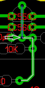
Hope i not too irritating, but if you gonna put time in input pole i have little tuneup to do at same time.
I attach Picture where you see input pulse (grey) going down trace hits BC560 before BC550 (blue) in teory one fires before the other out to symetri. Try making so that signal hits basis legs at both devices at same time so they fire synchronous to symetri.
Regards Ricky
Attachments
GB members listed - addresses still not received
badrisuper 2 PCB set
JethroTull 2 PCB set
milandks 4 PCB set
tjencks 2 PCB set
quanghao 2 PCB set
audionootje 4 PCB set
Meganinja 2 PCB set
gnat 2 PCB set
I kindly ask above listed remained GB members to send their address to:
esl@siol.net
Please prepare your address information in most exact form, like this:
1. line: Your diyAudio Forum Name (very very important)
2. line: Company Name (if not any please skip this line)
3. line: First Name Second Name (family name)
4. line: Street Name Street Number
5. line: Street or District Name (if not any please skip this line)
6. line: City Code Number (postal number) City Name
7. line: Province or State Name (if not any please skip this line)
8. line: Country Name
9. line: e-mail address (very very important)
I will prepare the Proforma Invoices for all of you already sent addresses, latest tomorrow.
Regards, L.C.
Thanks LC! Can't wait to receive those.
BTW, any news on the enclosures?
regards
Hi

First six on the list will be send out in a day or two.
The cases are calculated, photos made ... I will publish new thread, first just to send out all proformas here in VSSA.
Would like not to mess these two GB-s. Soon it will be.
Regards
- Home
- Vendor's Bazaar
- VSSA Lateral MosFet Amplifier