Post 2240: Hi Christophe
Gets different result in left part of image. If i scale aproximately same as your picture phase should clear visible start to get slow at 100 Hz and be about 52° lagging at 1hz, but if one scales in the lag starts much higher think 1khZ.
My software is Tina texas Instrument version which is free at their site.
May i ask you have Placed a 2200uF cap just before 47 ohm emitter resistor seen from rail for BC550/BC560 pair.
I see a Little lag at your image from 7 Hz and Down, so think you have simulated with cap size 22.000uf instead of 2.200uF.
And the different schematic versions doesn't change this aspect very much, think that newer versions are for the first version to run proberly in real World.
Ricky
Last edited:
Post 2242:
Yes ~4° at 20 Hz.
Andrej explained at another thread the funktion see http://www.diyaudio.com/forums/solid-state/237219-fet-hex-explendit-amplifier-26.html #251.
Ricky
Yes ~4° at 20 Hz.
Andrej explained at another thread the funktion see http://www.diyaudio.com/forums/solid-state/237219-fet-hex-explendit-amplifier-26.html #251.
Ricky
Last edited:
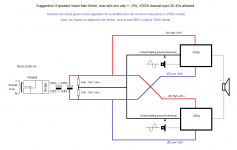
Hi Christophe, suggestion.
Now you have the sim file try make a copy and do the balanced version.
I have got balanced sim version up and running fine, details below for config:
1 - I used the simplified schematic that i attach as image.
2 - I used metallicus69 schematic for 2,2mF caps crossing, see link http://www.diyaudio.com/forums/vend...lateral-mosfet-amplifier-166.html#post3539303 #1660
3 - In the sim program i had to ad a virtuel ideal transformer (1:1) which primary pins were routed to pos amp speaker out and neg amp speaker out, and then secondary pins got ground and speaker out route. Else the sim program made strange sims because of pos/neg speaker out were referenced to ground.
In my sim it starts clipping, one standard module ~38,4V (8 ohm 2x45V supply), and in above config balanced, clipping starts ~75,8V (8 ohm 2x45V supply).
Christophe you can get copy of sim files, if the before mentioned sim program suits you.
Ricky
Attachments
Last edited:
BYRTT, nice idea to simulate bridge, while i suppose there is nothing more than Harmonic Distortions to be enhanced and showed in sims (and PSRR if we try).
On my side, i use LTSPICE, but i'm both not very experienced in sims and not too much interested by them: I prefer real life")
Will try to explore bridge operation of this amplifier, once i had finished a special mission: to compare it with a VFA version for educational purpose.
About the cap crossing, i worry about the increase of their voltage.
On my side, i use LTSPICE, but i'm both not very experienced in sims and not too much interested by them: I prefer real life
Will try to explore bridge operation of this amplifier, once i had finished a special mission: to compare it with a VFA version for educational purpose.
About the cap crossing, i worry about the increase of their voltage.
Last edited:
Post 2245: Heres sim data for measured voltage over mentioned caps.
Input 1,7V (+/-) sinus 1000Hz +/-45V rails 8 ohm resistor load.
Single module: 0,8V DC/2,44V AC
Balanced modules: 1,6V DC/2,58V AC
Input 1,7V (+/-) square 1000Hz +/-45V rails 8 ohm resistor load.
Single module: 0,8V DC/0,8V AC
Balanced modules: 1,6V DC/1,6V AC
Looks okay, maybe they need to be nonpolar ?
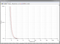
Groupdelay gets better when caps crossed, but then they also sits in their own Little floating virtuel ground spot.
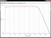
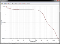
Heres sim for single module verse balanced version configured as mentioned in post 2244. Sim program Tina Texas Instruments (v9.3.50.40 SF-TI) downloaded free from their website.
Brown trace=single module, gray trace=balanced modules
Picture 1=BANDWITH/GAIN
Picture 2=PHASE-PLOT
Picture 3=GROUPDELAY
BR Ricky
Input 1,7V (+/-) sinus 1000Hz +/-45V rails 8 ohm resistor load.
Single module: 0,8V DC/2,44V AC
Balanced modules: 1,6V DC/2,58V AC
Input 1,7V (+/-) square 1000Hz +/-45V rails 8 ohm resistor load.
Single module: 0,8V DC/0,8V AC
Balanced modules: 1,6V DC/1,6V AC
Looks okay, maybe they need to be nonpolar ?
Groupdelay gets better when caps crossed, but then they also sits in their own Little floating virtuel ground spot.
Heres sim for single module verse balanced version configured as mentioned in post 2244. Sim program Tina Texas Instruments (v9.3.50.40 SF-TI) downloaded free from their website.
Brown trace=single module, gray trace=balanced modules
Picture 1=BANDWITH/GAIN
Picture 2=PHASE-PLOT
Picture 3=GROUPDELAY
BR Ricky
Attachments
Last edited:
What comparizons ? Same total power harmonic distortion ?It would be interesting to simulate harmonic distorsion and levels of them in balanced and single ended VSSA version...
I believe the main benefits will not been showed by sim: PSSR, RFI/RMI immunity, etc.
Oh, no. double size and sometimes less quality.Looks okay, maybe they need to be nonpolar ?
On my side, i'm not tempted by this arrangement: it makes the build less easy and even tricky, the two side of the bridge will be no more independent, on a physical point of view, a risk to have longer lengths to caps, more risk in case of failure etc.
Quote: 2247-2248
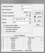
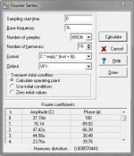
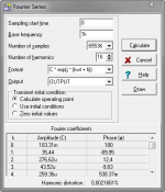
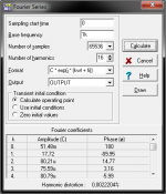
Hi here sim for single ended verse balanced version. Because i am hobbyist i don't at present have skills for the setup of real technician bench for distortion test, so i use the in program built in Fourier Analysis
For remarks it should be said KSC/KSA and ALF devices are not built in the program, so its a generic types used.
For all sims input is 1,7V (right before clipping), rails +/-45V, load 8 ohm resistor.
25.07V RMS out single ended = 78,56 WATTS.
50,13V RMS out balanced = 314,12 WATTS (From others this should be real world 2,5 x single ended) so balanced gets real world 196,4 WATTS.
Picture 1=Single ended v1.4x schematic
Picture 2=Balanced v1.4x schematic
Picture 3=Single ended v1.3 schematic
Picture 4=Single ended v1.4 schematic
The version 1.4x schematic is compiled of info from this hole thread, it should be close to the shipped copyrighted layout version. It can be seen from v1.3 to v1.4x in very small distortion digits the fixes for real world safe funktion.
Attachments
Quote BYRTT Post 2249: "The version 1.4x schematic is compiled of info from this hole thread, it should be close to the shipped copyrighted layout version. It can be seen from v1.3 to v1.4x in very small distortion digits the fixes for real world safe funktion."
Can you kindly post your .asc files for education and learning!
--gannaji
Can you kindly post your .asc files for education and learning!
--gannaji
Quote gannaji post 2250: Hi gannaji, after public v1.4 this thread went "Commercial sector", please respect.
kindly answer:
Your request say purpose is for education and learning hmmmm, then i say read this hole thread it is top stuff for education and learning, and when you have read hole thread you are able to compile same schematic as i have = learning. If you after have read the hole thread not are able to nearly understand circuit and compile nearly same schematic as shipped, then i claim your skills is at such level that if you got copy of mine v1.4x, you won't understand anyway = no learning.
Digging into this thread will also take you to 4 x other very hot VSSA version threads.
And remember i am hobbyist, so how true is my v1.4x.
Skeptical answer:
Truth is that v1.3 is splendeed for engineering education and learning, final version is just tuneup for real world stability and performance, what do you need this for ?
If you have hidden agenda/purpose behind request, for example build your own private high performance amp or go commercial production by your own, i suggest: Contact author to participate in group buy (for private amp), or negotiate with author about OEM possibility.
Last you could try request author for final version.
Ricky
BYRTT 8 PCB set
CaféNoir 6 PCB set
ColinAlex 8 PCB set
DavorXXL 6 PCB set
DuffyDawg 4 PCB set + 4 SMPS400
electromf 4 PCB set
badrisuper 2 PCB set
volavola 2 PCB set
JethroTull 2 PCB set
kp93300 2 PCB set
momomo67890 4 pcb set
ua3grn 6pcb set
mj777 2pcb set
mkusan 2pcb set
Odysseas 4pcb (2 pairs)
hcbonfim 2pcb set
Albrerta 2pcb set
dw1narso 2 pcb set (1 stereo) + extra output device pairs & isolators (for stereo if possible)
supernet 2 pcb set
milandks 4pcb set
tjencks 2pcb set
quanghao: 2pcb set
audionootje: 4pcb set (2x stereo)
tritosine 4pcb (2 pairs)
Bobo le Chat 2 pcb set
AP2 2pcb set+2pcb empity (i need this also)
Meganinja 2 set ( stereo )
mikvous 2 pcb set
Rick G 2 PCB set
kindhornman 2 boards
ravid 2 pcb set
siberia 2 pcb set
gnat 2 pcb set
potepuh 2 pcb set
metallicus69 4 pcb set
Ranchu32 2 pcb set
woofertester 4 pcb set
edbk 4 pcb set
Raj1 2 pcb set (or 6 if available)
analog_sa 3pcb set + extra output device pairs & isolators (for stereo if possible)
BYRTT 8 PCB set
CaféNoir 6 PCB set
ColinAlex 8 PCB set
DavorXXL 6 PCB set
DuffyDawg 4 PCB set + 4 SMPS400
electromf 4 PCB set
badrisuper 2 PCB set
volavola 2 PCB set
JethroTull 2 PCB set
kp93300 2 PCB set
momomo67890 4 pcb set
ua3grn 6pcb set
mj777 2pcb set
mkusan 2pcb set
Odysseas 4pcb (2 pairs)
hcbonfim 2pcb set
Albrerta 2pcb set
dw1narso 2 pcb set (1 stereo) + extra output device pairs & isolators (for stereo if possible)
supernet 2 pcb set
milandks 4pcb set
tjencks 2pcb set
quanghao: 2pcb set
audionootje: 4pcb set (2x stereo)
tritosine 4pcb (2 pairs)
Bobo le Chat 2 pcb set
AP2 2pcb set+2pcb empity (i need this also)
Meganinja 2 set ( stereo )
mikvous 2 pcb set
Rick G 2 PCB set
kindhornman 2 boards
ravid 2 pcb set
siberia 2 pcb set
gnat 2 pcb set
potepuh 2 pcb set
metallicus69 4 pcb set
Ranchu32 2 pcb set
woofertester 4 pcb set
edbk 4 pcb set
Raj1 2 pcb set (or 6 if available)
analog_sa 3pcb set + extra output device pairs & isolators (for stereo if possible)
mravlca 2pcb set
VSSA Transistor Matching
Of the people who have built the SSA/VSSA/TSSA, who matches transistors by measuring at operating current and voltage?
I am about to start building an SSA and a VSSA. I have bought 2SA970, 2SC2240, MJE340, MJE350, etc. I have tested 10 pcs from each batch at Ic = 2mA at Vce = 40V. The input pair for VSSA has a Vce of about 40V from my calculations.
I set Vce to 40V and then adjust Ib from very small to about where Ic= 4mA and measure Beta throughout.
The MJE transistors were measured at Ic = 10 mA.
The values for Beta leave me absolutely no pairs of NPN/PNP transistors that match.
Here are the ranges for Beta
MJE340STU 91.4 - 104.8
MJE350STU 144.0 - 155.2
2SC2240-GR 279.7 - 356.9
2SA970BL - 509.4 - 632.0
KSA1381ESTU 126.5 - 134.3
KSC3503DSTU 79.0 - 80.5
I need to find some KSC3503E.
My goal is to get matched pairs. I believe that offset will be easier to control and distortion will be lower with matched pairs.
Withing a particular part number, identical matches abound.
Suggestions and comments are welcome.
2SC3502E are just as good as the ones you look for, it just have a 200 Vce limit.Other then that it`s the same device. they are available on ebay.. i got some and they tested good.
2SC3502E 2SC3502 Trans GP BJT NPN 200V 0 1A 3 PIN TO 126 | eBay
2SC3502E 2SC3502 Trans GP BJT NPN 200V 0 1A 3 PIN TO 126 | eBay
Last edited:
- Home
- Vendor's Bazaar
- VSSA Lateral MosFet Amplifier