I'm sure it is not and will had a lot of evils. Don't ever think of it. I'm sure that the group delay curve of this amp is perfect in the audio range and far away up to radio frequencies.Can you guide if its worth.
Don't forget there is a passive low pass filter before the input, very important for no overshoot, good sound and TIM, so, what you measure is not the amplifier bandwidth.
Last edited:
Hi Christophe
When i get modules i start with Andrejs recommended and sure ok.
But it iritates me when simulating, my old DC coubled Sansui AU-D9 goes linear from DC way out, but for sure VSSA has way out even higher.
Attach image green line VSSA, Brown line look strait line bottom at Sansui from DC up.
Ricky
When i get modules i start with Andrejs recommended and sure ok.
But it iritates me when simulating, my old DC coubled Sansui AU-D9 goes linear from DC way out, but for sure VSSA has way out even higher.
Attach image green line VSSA, Brown line look strait line bottom at Sansui from DC up.
Ricky
Attachments
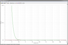
Well, Ricky, it represent at 40Hz 0.1ms, mean less than (if i don't mistake) 2° of phase error or 3.5cm of error distance in air.Attach image green line VSSA, Brown line look strait line bottom at Sansui from DC up.
Go figure !
41 hz is the lowest note from a musical instrument (basse) where phase coherency can matter.
(with kick drums of witch i have no idea).
Here the group delay of the best speaker i know in this domain, just to compare:
http://www.moonaudio.fr/Photos%20taille%20affichage/group%20delay.jpg
750µs at 40Hz: while you measured 100µs.
If what you listen sounds ok in the basses (as i presume) better forget about this.
Last edited:
Nice to have explanation to be calm.
But i just sits waiting for Semelabs ALFs and gets ideas for tuneup.
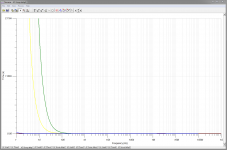
Attach new image:
Green = VSSA 2200uF default
Yellow = VSSA 15000uF Panasonic FC
Blue = 22f mentioned before
Brown = Sansui (under the blue line)
I will stop here thanks
Ricky
But i just sits waiting for Semelabs ALFs and gets ideas for tuneup.
Attach new image:
Green = VSSA 2200uF default
Yellow = VSSA 15000uF Panasonic FC
Blue = 22f mentioned before
Brown = Sansui (under the blue line)
I will stop here thanks
Ricky
Attachments
Last edited:
Hi Christophe,In the previous description, i forgot to precise that the input stage provide yet a x10 voltage gain (470/47 ohms) to the signal. Low enough, in regard to the total gain of the transistor to keep a low distortion factor. Too late to edit.
And to precise that the mosfet used as power devices are lateral, means they have a negative temperature curve, making unnecessary to add any compensation temperature network to avoid quiescent current run out, with their evils. The quiecent current has been set enough to provide a Class A working condition in normal listening levels, and, i suppose, near the point where transconductance/temperature curve is flat.
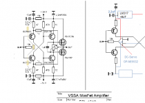
With regards to VSSA V1.4 schematic, is the feedback 1k/47R? What is the purpose of the 1uF parallel with 2.2mF(10V)? In other amps, 47R is just connected to ground.
I hope to learn more on this VSSA as much as I enjoy listening to it everyday.
Cheers!
WP
Yes, the feedback is the 1K and 1K/47R determine the closed loop gain of the amplifier.With regards to VSSA V1.4 schematic, is the feedback 1k/47R? What is the purpose of the 1uF parallel with 2.2mF(10V)? In other amps, 47R is just connected to ground.
The 10µF is here to minimize the inductance effect in the big 2.2mF, and reduce the impedance at HF.
About this use of CSS, i asked L.C. when he had published its schematic. My understanding is that CSS (supposed to be an infinite impedance) is here just to provide DC for the input's stage transistors and stabilize their polarization, filtering further the rail ripples.
While those caps makes a ground for small AC signals.
As reported by BYRTT, this has for consequences that the X10 gain of the input stage is reduced to 1 for DC. A good way to stabilize offset.
The negative point is it introduce a low pass filter. As those caps have an influence on the signal quality, this explain why L.C. has take great care to listen to various caps here and chose the best ones. We have to remember that, contrary at common believes, good Electrolytic capacitances, despite their inductance's problem, present very low distortions, among the best of the best capacitances. They are excellent devices.
I hope L.C. will not be upset by this way to analyze its circuit from only the schematic, and that i don't make mistakes. He is the only one to know deeply the why and how.
Please forgive me but I would like to remove my name from this group buy. That will make room for someone else who had wanted a pair.
Thanks, Terry
BYRTT 8 PCB set
CaféNoir 6 PCB set
ColinAlex 8 PCB set
DavorXXL 6 PCB set
DuffyDawg 4 PCB set + 4 SMPS400
electromf 4 PCB set
badrisuper 2 PCB set
volavola 2 PCB set
JethroTull 2 PCB set
kp93300 2 PCB set
momomo67890 4 pcb set
ua3grn 6pcb set
mj777 2pcb set
mkusan 2pcb set
Odysseas 4pcb (2 pairs)
hcbonfim 2pcb set
Albrerta 2pcb set
dw1narso 2 pcb set (1 stereo) + extra output device pairs & isolators (for stereo if possible)
supernet 2 pcb set
milandks 4pcb set
tjencks 2pcb set
quanghao: 2pcb set
audionootje: 4pcb set (2x stereo)
tritosine 4pcb (2 pairs)
Bobo le Chat 2 pcb set
AP2 2pcb set+2pcb empity (i need this also)
Meganinja 2 set ( stereo )
mikvous 2 pcb set
Rick G 2 PCB set
kindhornman 2 boards
ravid 2 pcb set
evette 6 PCB set
siberia 2 pcb set
gnat 2 pcb set
potepuh 2 pcb set
metallicus69 4 pcb set
Ranchu32 2 pcb set
woofertester 4 pcb set
Please remove my nane also..And thanks for the effort. Regards Evette
Removed your "evette 6 PCB set" added 4 for me, hope it fits in

BYRTT 8 PCB set
CaféNoir 6 PCB set
ColinAlex 8 PCB set
DavorXXL 6 PCB set
DuffyDawg 4 PCB set + 4 SMPS400
electromf 4 PCB set
badrisuper 2 PCB set
volavola 2 PCB set
JethroTull 2 PCB set
kp93300 2 PCB set
momomo67890 4 pcb set
ua3grn 6pcb set
mj777 2pcb set
mkusan 2pcb set
Odysseas 4pcb (2 pairs)
hcbonfim 2pcb set
Albrerta 2pcb set
dw1narso 2 pcb set (1 stereo) + extra output device pairs & isolators (for stereo if possible)
supernet 2 pcb set
milandks 4pcb set
tjencks 2pcb set
quanghao: 2pcb set
audionootje: 4pcb set (2x stereo)
tritosine 4pcb (2 pairs)
Bobo le Chat 2 pcb set
AP2 2pcb set+2pcb empity (i need this also)
Meganinja 2 set ( stereo )
mikvous 2 pcb set
Rick G 2 PCB set
kindhornman 2 boards
ravid 2 pcb set
siberia 2 pcb set
gnat 2 pcb set
potepuh 2 pcb set
metallicus69 4 pcb set
Ranchu32 2 pcb set
woofertester 4 pcb set
edbk 4 pcb set
Hi,
The charm of the amplifier is right its simplicity and can offer very high performance. as the current feedback. it is obvious that we can continue to develop around this circuit, but the risk is that it becomes complex as other amplifiers.
it is my opinion that you can groped small improvements, just to eliminate the drift offset.
It is absolutely not my intention to interfere with the design of LC, except that I do not know in which release scheme refers to the pcb (sorry, the thread is long, I did not follow). maybe my idea of the multi-turn trim is already applied?
Attachments
Hi AP2 
Very nice that you thinking about VSSA.
Well, let me tell you about output DC offset in VSSA. It starts at power on with -0,2 mV than it drifts from 0,2 mV to 0,8 mV when operating.
If you want uV region stability than I suggest you to use DC servo, otherwise forget about DC offset, bias, etc. because both are more stable than in any other design.
On my experience, DC servos present a generic low frequency noise not better than those numbers. I've read an input from Bob Cordel confirming this.It starts at power on with -0,2 mV than it drifts from 0,2 mV to 0,8 mV when operating. If you want uV region stability than I suggest you to use DC servo
Well, 1mV produces 0.125µw of power, outside of any audible frequency and will not move your bass speakers for more than some µm... low under their mounting precision...
I suggest, for those who think to a servo, here, to better worry about their " Cerveau* ".
*French translation for "Brain".
Last edited:
If this is supposed to be the case, then there is something amiss with my modules. Either that, or I have completely mis-adjusted something...Well, let me tell you about output DC offset in VSSA. It starts at power on with -0,2 mV than it drifts from 0,2 mV to 0,8 mV when operating.
I do not have my notes in front of me as I type, but ... My offset was difficult to adjust to single digits, using one, or two meters. This is in contrast to the bias, which adjusted fairly easily. (I have done this twice now, because I tested at two different supply voltages, and about to do it for a third time later this week.)
The drift from a cold start to stable heatsink temperature at quiescent current (non-operating) was significant. I believe I spent an hour-or-two testing the bias and offset, inputs shorted, including time to cool to room temps, and stabilize, with heatsinks rated 0.65C/W.
@anyone else: This is more of a technical issue. Do not take this as a reflection on the sound (which I have found to be excellent in all test so far). A few mV offset plus or minus does not change what comes out of a speaker.
If this is supposed to be the case, then there is something amiss with my modules. Either that, or I have completely mis-adjusted something...
I do not have my notes in front of me as I type, but ... My offset was difficult to adjust to single digits, using one, or two meters. This is in contrast to the bias, which adjusted fairly easily. (I have done this twice now, because I tested at two different supply voltages, and about to do it for a third time later this week.)
The drift from a cold start to stable heatsink temperature at quiescent current (non-operating) was significant. I believe I spent an hour-or-two testing the bias and offset, inputs shorted, including time to cool to room temps, and stabilize, with heatsinks rated 0.65C/W.
@anyone else: This is more of a technical issue. Do not take this as a reflection on the sound (which I have found to be excellent in all test so far). A few mV offset plus or minus does not change what comes out of a speaker.
My VSSA here is having DC offset 0 mV +/- 1 mV max. no DC servo required
oh..thank,Hi AP2
Very nice that you thinking about VSSA.
Well, let me tell you about output DC offset in VSSA. It starts at power on with -0,2 mV than it drifts from 0,2 mV to 0,8 mV when operating.
If you want uV region stability than I suggest you to use DC servo, otherwise forget about DC offset, bias, etc. because both are more stable than in any other design.
I not think this amp have issue, i read some last post, perhaps I did not understand if they relate to a problem of offset.
It is not my intention to modify your amp.
Independently from your design, we can also discuss but perhaps it would take another thread.
Regarding "DC servo" (like everything else), has pros and cons. the important thing is to know what you want to do.
P.S. in which post, I can find the schematic last?
@Esperado: A DC-Servo well developed (not copied from another who may not know how it works), runs under the minimum frequency of the low band, what kind of noise you think there is? so if your lower limit is 5 Hz, it work under.
When I work, I do not look at what Bob Cordel says or others. with big respect.
Regards
Last edited:
I, neither, never read electronic books, but i like Bob's inputs for several reasons: He is experienced, he is honest in a scientific meaning, he has not too much ego, he never talk about things he is not sure of, he have a very clear and simple way to think and explain.When I work, I do not look at what Bob Cordel says or others. with big respect.
Here his input on this servo's subject:
http://www.diyaudio.com/forums/solid-state/240712-cfa-topology-audio-amplifiers-9.html#post3598137
He don't think is is generic, i believe he had experienced this point more than me. The result is the same, i had never an amp with less DC than the numbers provided by L.C. Under 5 or 10mv, there is nothing i try to improve, on my side.
One thing i can bet my horse is, as the VSSA has a gain of ~1 at DC, a servo will not really improve the things, if i an not mistaken.
L.C. ?
Last edited:
Using the same trim pots as on the production modules?My VSSA here is having DC offset 0 mV +/- 1 mV max. no DC servo required
You posted once that you plan to replace the trimmer with stacked SMD resistors, or something to that effect.
I, neither, never read electronic books, but i like Bob's inputs for several reasons: He is experienced, he is honest in a scientific meaning, he has not too much ego, he never talk about things he is not sure of, he have a very clear and simple way to think and explain.
Here his input on this servo's subject:
http://www.diyaudio.com/forums/solid-state/240712-cfa-topology-audio-amplifiers-9.html#post3598137
He don't think is is generic, i believe he had experienced this point more than me. The result is the same, i had never an amp with less DC than the numbers provided by L.C. Under 5 or 10mv, there is nothing i try to improve, on my side.
One thing i can bet my horse is, as the VSSA has a gain of ~1 at DC, a servo will not really improve the things, if i an not mistaken.
L.C. ?
It depends on the fluxation of the input bias current and voltage. With an amp stable at lets say +/-5mV paired with an opa2376 will because of the zero current in the integrator feedback loop get the DC level of the amp close to the opamps dc offset level => max : 25uV + delta 1uV/kelvin
- Home
- Vendor's Bazaar
- VSSA Lateral MosFet Amplifier