Mr Evil said:Looks interesting.
The term "current feedback" is ambiguous - it usually means that the feedback is proportional to output current, but is also sometimes used to mean that feedback is to a low-impedance node, although neither is the case here. It would be better to described the output stage as having a common-base input.
Also... ULG? I don't recall having seen that acronym before. From the way you've used it I assume it means unity-gain frequency?
How about replacing Q79/80/81/82 with a pair of JFETs, and cascoding them with another pair of JFETs instead of Q13/10? It would greatly simplify biasing, reducing component count by 6.
True, calling it common base input would be more appropriate. Otherwise, the whole thing could be redesigned as a true current feedback by inverting the opamp inputs and feeding the other output stage input. There are some issues with the frequency compensation, though, so I preferred the current approach.
ULG stands for Unity Loop Gaing, aka the frequency at which the loop gain is 0dB.
Interesting idea, I'll look into that. Just when I thought I'm done with experimenting with this topology
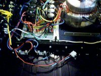
BTW, this is an experimental model on my bench, feeding for the moment a farm of 4ohm/50W resistors
atiq19 said:LME49713 looks pretty good. Can we use it for OPA637?
Does anyone have any experience with this new chip from NS?
Not sure, that's a current feedback opamp. Here's a list of opamps that I have tried so far, with good results:
OPA637
THS4601 (SOT8)
THS4631 (SOT8)
THS4031 (SOT8, bipolar)
AD8065 (SOT8, 12V)
AD829 (SOT8, bipolar)
ADA4898 (SOT8, bipolar)
LM7171 (bipolar)
Syn08 , could you post the .asc's for this design (bjt/mosfet).
Another question, could the ksc1845/a992 be substituted for
the 2sc2240/2sa970. I have 50 each of the ksa's /20 each
of the 1381/3503's.
I am glad you posted the BJT version, as I also have 20 ea.
of njw0302/0281.
If I use a 6 X 9 board and keep my layout compact , would
just 2 decoupling "pairs' be used on the OPS rails ?
OS
ostripper said:Syn08 , could you post the .asc's for this design (bjt/mosfet).
Another question, could the ksc1845/a992 be substituted for
the 2sc2240/2sa970. I have 50 each of the ksa's /20 each
of the 1381/3503's.
I am glad you posted the BJT version, as I also have 20 ea.
of njw0302/0281.
If I use a 6 X 9 board and keep my layout compact , would
just 2 decoupling "pairs' be used on the OPS rails ?
OS
Unfortunately I am using PSpice so you have to recapture the schematic in LTSpice.
The Fairchild pair will do just fine.
The decoupling is a matter of board and grounding design. To be on the safe side, I always lately use decoupling for each power device.
BTW, comparing to the MOSFET version the bipolar version is somehow worse in terms of pulse response (more ringing, requires adjusting the rise/fall times to compensate, etc...). This is at >100KHz so I'm pretty sure it's not audible, and can also be adjusted by tweaking the compensation. I'm not very experienced in bipolar output stages, so further optimizations are welcomed, both in the bias spreader and pulse response. I've tried last night one of the Bob Cordell's bias spreaders, but it doesn't seem to do better in terms of thermal compensation (or I don't know what/how to measure).
Even simpler.
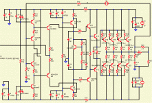
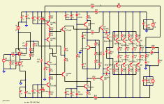
Ok I understand many of you guys don't really like opamps If you are happy with a little more performance hit, here's an even further simplified bipolar version of the VSOP amp.
Take this as a proof of concept. Althought it's zumming on my bench right now, I have not fully characterized this and I do not have plans to build it as a final construction (case, etc...). It also needs a few extra additions, not figured in the attached schematic, see below.
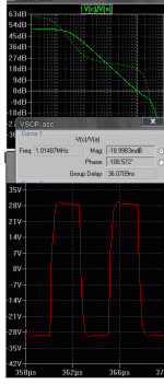
There are a few important changes. First, this is a full current feedback implementation. Note the ultra simplified frequency compensation (L6, R253), works like a charm with an ULG of about 3MHz and a phase margin of about 70 degrees.
Also note of of Bob Cordell's versions of bias spreader. Works good from a DC perspective, bias is solid, however I find little advantage to the simpler NJL series diode string and current feedback driver, as in my previous post. In fact, from an AC perspective, it's a little worse (less phase margin and a little more distortions).
Distortions are around 0.009% at 20KHz, 400W output into 4ohm.
To have a fully working amp, this proof of concept needs a) an unity gain buffer at the input. As it is, the input impedance is 1Kohm, to small for practical purposes and b) a servo; as any current feedback construction, the offset is pretty large. None of this should be a problem for an experimented constructor...
Ok I understand many of you guys don't really like opamps
Take this as a proof of concept. Althought it's zumming on my bench right now, I have not fully characterized this and I do not have plans to build it as a final construction (case, etc...). It also needs a few extra additions, not figured in the attached schematic, see below.
There are a few important changes. First, this is a full current feedback implementation. Note the ultra simplified frequency compensation (L6, R253), works like a charm with an ULG of about 3MHz and a phase margin of about 70 degrees.
Also note of of Bob Cordell's versions of bias spreader. Works good from a DC perspective, bias is solid, however I find little advantage to the simpler NJL series diode string and current feedback driver, as in my previous post. In fact, from an AC perspective, it's a little worse (less phase margin and a little more distortions).
Distortions are around 0.009% at 20KHz, 400W output into 4ohm.
To have a fully working amp, this proof of concept needs a) an unity gain buffer at the input. As it is, the input impedance is 1Kohm, to small for practical purposes and b) a servo; as any current feedback construction, the offset is pretty large. None of this should be a problem for an experimented constructor...
An externally hosted image should be here but it was not working when we last tested it.
By syn08 -so further optimizations are welcomed, both in the bias spreader and pulse response.
I was about to give up on the BJT version (oscillation city) ,but
did not. your mosfet version sims very well.(first shot).
For my BJT version I "borrowed" some of roender's folded
techniques.
http://www.diyaudio.com/forums/attachment.php?s=&postid=1349109&stamp=1194852081
What I came up with is STABILITY
 wow..
wow..Thanks for inspiration.. I did add some current sources
to the diamond (psrr) and still have 100mv offset, but
on the plus side 50+db OLG and 1mhz UG. This sucker
is fast.. I retained at least 70+ v/us SW. Your advice to
trim offset and compensate input with a unity gain op-amp
seems to be the best way.
OS
Attachments
Yes , this topology is much more "picky" than the standardbut I doubt he knows / understands anywhere near what you need to design an amplifier such as this.
"blameless" , but can be much faster. (I am hitting 100v/us now
, but it rings a little.)
OS
Very good work , syn... I did not mean to mess with your circuit too much but I don't have as much to work with (my KSA's /NJL's
and LT4).
I did get the 110v /uS slew (with roenders crude compensation)
at 22p (same as in your 2-pole). Only 1mhz (exactly) UG
and 53db OLG. (attached)
I feel bad using the crude compensation but like the current sources.
This is SO much better than a blameless as far as speed.
THD was a problem but I reduced that to .006% by "tinkering".
PS. another advantage of this design over roenders and MJL's
folded amps is that "sticking" at the rails is minimized (overdriven/clip), could it be the diamond ??
OS
Attachments
Increasing slew rate in a folded cascode is a simple matter of increasing the cascode current. High slew rate makes for some impressive oscilloscope pictures, but it doesn't really do much for the sound though.ostripper said:... I did get the 110v /uS slew (with roenders crude compensation)
at 22p (same as in your 2-pole)...
Increasing slew rate in a folded cascode is a simple matter of increasing the cascode current. High slew rate makes for some impressive oscilloscope pictures, but it doesn't really do much for the sound though
It is all a tradeoff , even with this amp. I will only get 70v/uS
with 27p Cdom's but no ringing and overshoot.
With the current sources I was able to use mpsa's ,ksa's ,
2sc's .. any device for input stage with VERY good stability.
Stability is more important than speed to me , so when I see
a design that can do BOTH , I'm impressed.
At the 110v slew , I saw that I also had a 70 degree phase margin which confirms the designers readings. I prefer 80+..
OS
I did the suggested voltage follower and all , played with the
gain , compensation , biasing with all stages and got:
.003% thd20 @ 80vp-p - 80v/us slew - 1.13 mhz UG @ 81 db
phase margin (-11 db @180 degrees "a dip"- absolutely will not oscillate) 55db !! OLG.
OLG.
I am absolutely making this for the genesis stealth replacement.
The op-amp front end will make offset/LP filter/gain so easy.
I do have a less than desirable "LT1057" model for my OP-amp
and IT showed .002% by itself , so the vsop is
around .001 .
OS
gain , compensation , biasing with all stages and got:
.003% thd20 @ 80vp-p - 80v/us slew - 1.13 mhz UG @ 81 db
phase margin (-11 db @180 degrees "a dip"- absolutely will not oscillate) 55db !!
I am absolutely making this for the genesis stealth replacement.
The op-amp front end will make offset/LP filter/gain so easy.
I do have a less than desirable "LT1057" model for my OP-amp
and IT showed .002% by itself , so the vsop is
around .001 .
OS
Attachments
By mr evil - If you like speed, you might try investigating class-AB input stages. They can give incredible slew rates due to their high current capability.
I am not a "speed demon" , more of a "abuser" it is the
simplicity and stability of this amp that caught my fancy.
I also like the fact that now I can put any small device
in for the inputs (bc's/ ksa/mpsa/2n's) , worst that will
happen is more THD , less OLG/UG.. but it will still work
and not oscillate.
The output stage and Vbe I know work (for real) it is
the VSOP VGS that I will do "a leap of faith" on.
A unity gain OP-amp buffer.. you can't screw that up
 .
.It gets 40c here soon .. so all the vsop stages are 2-7ma.
real
as well... what the hell. I have heard diamonds give
nice sound (tried the krill), I have nothing to lose but
100 sq. inch of FR-4
OS
Unless there's anything outstanding, this one goes to the PCB manufacturing ASAP. Speak now, or forever hold your peace 
Changes:
- No more dual pole compensation, look at the 22uH inductive compensation
- Added active clamps, no more sticking, overload recovery is clean as a baby. Worth two extra transistors and a few diodes (200V breakdown required!).
- LME49710 single opamp, this is the best cost/performance device and it comes in DIP8. Still no servo required, offset is under 5mV.
The experimental model shows THD20 under 10ppm (around 5ppm, actually) @360W into 4ohm, 120V/us slew rate, rise time defined by the input RF filter.
Still not decided about the bipolar version... Will decide after finishing the MOSFET boards. I really want to build a bipolar version with thermaltraks, but I can't decide for the best configuration. Unfortunately, simulations are pretty much useless here
An externally hosted image should be here but it was not working when we last tested it.
By syn08 -I really want to build a bipolar version with thermaltraks, but I can't decide for the best configuration. Unfortunately, simulations are pretty much useless here
Do you mean Bjt simulations in general or just with the t-trak's ?
I am serious about building a VSOP, I even finished a nice
PS for some form of it (attached). +- 77v @ 30A's is too much
for what I have now.
Would I be in error to power the op-amp separately (2'nd
trafo w/ regulated +- 15v supply.
I really want to just have the VSOP on it's own board with
the IC's separate. Do you see any big issues with what
I previously posted ? I thought you abandoned this thread
so I just went solo with the bjt version. The refinement
I've done since the last post is to "split" the gain between
the IC and the VSOP. I am not looking for 10 PPM , just
stability and simplicity (I'm happy with 50ppm).
Unlike others, I am truely interested in this topology but
only have 20 NJW's (0281/0302) to do the OPS with.
OS
Attachments
- Status
- This old topic is closed. If you want to reopen this topic, contact a moderator using the "Report Post" button.
- Home
- Amplifiers
- Solid State
- VSOP amp


