")
Akabak
I would like to try a quick mock-up of a foamcore DCR using the TC9FD driver. I have folded a single A1 size sheet into a square cross-section column: internal dimensions 142mm x 142mm x 830mm with a divider 2/3 along, forming 2 chambers of 11.09L and 5.55L. I would like front facing ports so that I can place the speakers against the wall.
I am still learning Akabak, does the script I am using to simulate look OK?
Code:
System 'TC9FDDCR'

Def_Driver 'TC9FD'
	Sd=36.3cm2
	Bl=3.01Tm
	Qms=2.73
	Qes=1.33
	Mms=2.4g
	fs=124.86Hz
	Vas=1.24L
	Le=0.05mH
	Re=6.32ohm

Driver Def='TC9FD' 'Driver1' Node=1=0=200=400  | connect driver here node 1=amp, 0=GND, 200=front cone face, 400=rear cone face

Enclosure  'Large Chamber'  Node=400  Vb=11.09L  Qb/fo=0.707  Lb=55cm

Enclosure  'Small Chamber'  Node=300  Vb=5.55L  Qb/fo=0.707  Lb=27.5cm

Duct	'Port1'  Node=400=401    dD=4.1cm  Len=8cm  | port from large chamber to room

Duct	'Duct1'  Node=400=300    dD=4.1cm  Len=3cm  | duct between small chamber and large chamber

Duct	'Port2'  Node=300=301    dD=4.1cm  Len=8cm  | port from small chamber to room

Radiator 'RadDriver1' Def='Driver1' Node=200  | Radiator element on Driver1

Radiator 'RadPort1' Def='Port1' Node=401  | Radiator element on Port1

Radiator 'RadPort2' Def='Port2' Node=301 | Radiator element on Port2Looks good. You can add stuffing and lower Q in chambers down to 0.2 and that will help reduce resonances. You can also add effect of baffle step losses and diffraction of front baffle and place radiators for vent on front with more specifications on the radiator element. Look at examples in manual.
Well, I put a single speaker together, and found it a little disappointing regarding bass extension and very bright. Even at quite modest volumes I am starting to get overexcursion. I will attempt to stiffen the walls with struts and add more damping and if that doesn't work, alter the tuning. I prefer the bass of the cornu spiral as things stand.
Pardon my stupidity but what is a BSC filter? Is it some kind of passive equalization?
Baffle Step Compensation. It's a circuit to help with the "loss" of some of the low frequencies. You lose a few dB of low frequencies due to the way they travel once they leave the driver. If you have what you believe to be a woofer and tweeter with the same SPL (sound pressure level= loudness), the tweeter will sound louder without BSC.
If you Google BSC or Baffle Step Compensation, you'll find a lot of info about it.
Mike
Thanks, I see it is an attenuation in the frequencies above where the bass starts to roll off. You can take away but you can't add. I'm using the TC9FD18-08 as a full range driver above 140hz and an LT250 as a subwoofer in the same cabinet. The TC9 has an impedance of 8 ohms while the LT has an impedance of 2 ohms. The driver's sensitivity is nearly the same. So the low impedance of the LAT will present a tiny load to the amp and concentrate most of its power across that load. I think?
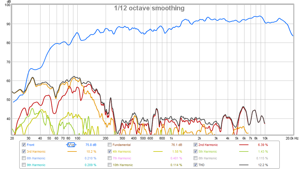
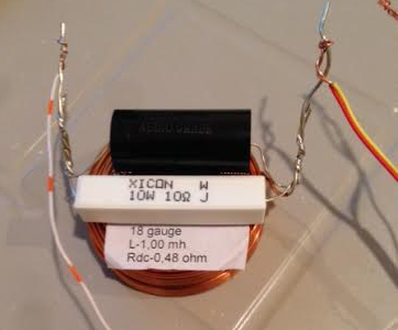
This was the BSC filter I used - it attenuates the HF quite a bit so sensitivity of speaker is down to maybe 76dB at 2.83v at 1m overall but gives a very nice balanced bass presentation. The 0.47uF cap is optional and boosts the HF a bit for more sparkle. It is 1mH and 10ohm in parallel.
xrk971,
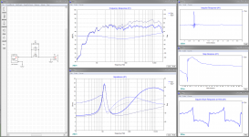
Visuals to BSC talk : ) in that traced your post 67 plot without BSC to a frd file and combined it with TC9 zma file had on HDD.
At first plot graphs grey trace is without BSC network and blue is the corrected system, at second plot blue is without capacitor grey is with 0,47uF and green is 1,5uF.
mr2racer,
If interested here tools you can use to create system impedance plot you talk about for TC9FD18-08 and LT250 build.
Attached below is a zma-file impedance plot data for TC9 driver in free air, also get a zma-file or plot for LT250 then trace plot and export as zma-file.
Free program FPGraphTracer : fprawn labs to scan traces on picture files showing plots and export as frq response/frd-file or impedance/zma-file.
Free modeling program XSim http://www.diyaudio.com/forums/multi-way/259865-xsim-free-crossover-designer.html.
Link those files to respective drivers into XSim plus add XO components to see impedance plot changes, frq response plot is also possible via either real live measurement data or trace responses from datasheet and extract predicted BSC. Free program TheEdge to predict BSC Tolvan Data.
Attachments
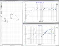
Thanks for the sims Byrtt! It looks like the 0.47uF is not doing much so just leave it out. If you want a HF boost then the 2.2uF seems like the value to have. I guess 1uF would have some audible effect as well.
Btw, if folks are interested, I found very cost effective 2.2uF and 1uF 250v MKP film caps here:
Free Shipping 10pcs, CBB 105J 250V 1UF P16mm Metallized Film Capacitor-in Capacitors from Electronic Components & Supplies on Aliexpress.com | Alibaba Group
Free Shipping 10pcs, CBB 225J 250V 2.2UF P15mm Metallized Film Capacitor-in Capacitors from Electronic Components & Supplies on Aliexpress.com | Alibaba Group
I have used cheap ferrite cored ones and they sound fine. Don't need large gauge air cored ones at all. The one I used here was before I knew better. My recent Tabaq used $0.50 ones rated for maybe 0.35A ferrite cores. Similar to this.
Online Shop 10 x 1mH 350mA 6x8mm 10% Ferrite Core Shielded Radial Lead Inductor Black|Aliexpress Mobile
Have a listen to what a 50 cent inductor and a 20cent resistor can sound like for a BSC in a Tabaq.
http://www.diyaudio.com/forums/full-range/88787-tabaq-tl-tang-band-125.html#post4691749
http://www.diyaudio.com/forums/atta...68984-tabaq-tl-tang-band-tabaq-clip-mg-01.asc
Change the extension from asc to MP3 to listen.
Last edited:
It sort of blew me away with the sound quality thru cheap inductors too. Small 3in drivers like this rarely see more than a few watts maybe 4 at most. The 0.35 amp rating is plenty and really it's meant as the limit at which the inductance rating is accurate. At higher currents the value changes a bit but that's not noticeable.
It's surprising they don't sell these at audio stores - well they wouldn't make any money for one thing. Much better to peddle $10 air cores made of 18ga copper wire.
It's surprising they don't sell these at audio stores - well they wouldn't make any money for one thing. Much better to peddle $10 air cores made of 18ga copper wire.
- Status
- This old topic is closed. If you want to reopen this topic, contact a moderator using the "Report Post" button.
- Home
- Loudspeakers
- Full Range
- Viva la Vifa! Curvy Cabinet DCR with TC9FD