Hi Bix,
the ROHS conform is still available as IRFP240PBF (Pb free or less than 0,1% Pb). So no problem to use this one
BR
Günni
I managed to track down original locally
") thanks for your advice though, good to know.
thanks for your advice though, good to know.Hi Hugh, things are progressing nicely. I’ve got all parts except a bunch of caps. I’m gathering parts for another build also, so will add the missing caps to that order.
Lining up two builds for the winter nights.
I managed to find a great local source for discontinued parts, so I’m stocking up for the future. Thanks for your advice earlier with regards to local suppliers. My guy was greatfull for the business. The parts weren’t as nicely packaged and labeled like some of the larger companies, but he has stock and they don’t. Shop local and support your community.
Hopefully start stuffing boards in a week or so.
How are you? What’s happening with those monster FETs you scored?
Lining up two builds for the winter nights.
I managed to find a great local source for discontinued parts, so I’m stocking up for the future. Thanks for your advice earlier with regards to local suppliers. My guy was greatfull for the business. The parts weren’t as nicely packaged and labeled like some of the larger companies, but he has stock and they don’t. Shop local and support your community
.Hopefully start stuffing boards in a week or so.
How are you? What’s happening with those monster FETs you scored?
Ah, those monster mosfets will be pressed into service when I have figure out a better pcb for that circuit; it's a variant of the ALPHA and X and I are considering it. These mosfets would be ideal for this amp, they are rated at 300W 150V 73A and quite easy to drive with a low cap gate.
I usually have two or three projects on the go but I will let you know what happens!
Hugh
I usually have two or three projects on the go but I will let you know what happens!
Hugh
C8 OPTN what is this?
I ran a spice sim on the circuit with different options for cap C8.
The circuit seems to be happy (in sim, anyway) with onwards of 67pf in this position. I think I put a 100pf as a standard value in my first 2 boards. (simmed with IRFP250 and 2SC5200).
Thanks for the info. I’ve got sets of irfp240 and 2sc5200. I haven’t tried spice yet. All my we Mac browsing etc is done with my iPhone. My pc is in a cupboard collecting dust for some time. Maybe I’ll resurrect it for spice and easier typing of replies and questions on this forum, one finger typeing is pretty slow. I haven’t used spice before but see there is thread all about it. So much to learn...
Hi,
I have been very impressed by the comments of the people who have built this amplifier about the quality of the sound and even some one says that he sound a little like a tube amplifier
Since I have made some tube amplifier based on the Baby Huey thread : EL84 Amp - Baby Huey I wanted to give a try to this semicoductor amplifier. I was already convinced by the quality of modern MOSFET as I use them to replace cathode follower in tubes amplifier, but I wanted also to get rid of the expensive and heavy output transformer...
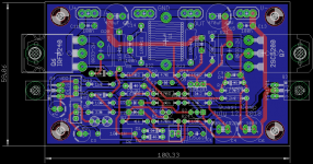
I started from a schematic kindly send by Prasi and I decided to make a new PCB. Why another one ? There is already so many nice PCB on this tread ! Well, my target for a semiconductor amplifier was to make it as slim as possible, let say at least less than 80 mm high, therefor I wanted to have a PCB of less than 60 mm high ! In addition I did not want to have the power transistors under the PCB to have a better access to them and to make assembly easier.
I am planning to use a box with heatsink on the sides like this one : Mini Dissipante 2U 250mm frontale 10mm ARGENTO coperchi in alluminio 2mm e retro 3mm and to use a 300 VA transformer with two 35 V AC 4.3 A outputs, I will also use Prasi CRC power supply board.
Please tell me if you think that this is possible and that a new Quasi could be on the way ?
Thaks,
Marc
I have been very impressed by the comments of the people who have built this amplifier about the quality of the sound and even some one says that he sound a little like a tube amplifier
Since I have made some tube amplifier based on the Baby Huey thread : EL84 Amp - Baby Huey I wanted to give a try to this semicoductor amplifier. I was already convinced by the quality of modern MOSFET as I use them to replace cathode follower in tubes amplifier, but I wanted also to get rid of the expensive and heavy output transformer...
I started from a schematic kindly send by Prasi and I decided to make a new PCB. Why another one ? There is already so many nice PCB on this tread ! Well, my target for a semiconductor amplifier was to make it as slim as possible, let say at least less than 80 mm high, therefor I wanted to have a PCB of less than 60 mm high ! In addition I did not want to have the power transistors under the PCB to have a better access to them and to make assembly easier.
I am planning to use a box with heatsink on the sides like this one : Mini Dissipante 2U 250mm frontale 10mm ARGENTO coperchi in alluminio 2mm e retro 3mm and to use a 300 VA transformer with two 35 V AC 4.3 A outputs, I will also use Prasi CRC power supply board.
Please tell me if you think that this is possible and that a new Quasi could be on the way ?
Thaks,
Marc
Attachments
Nice work, Marc.
I'm quite excited to see how you go with this design.
I enjoyed building my 'Phunk - Borg' Quasi and just waiting on it's home to turn up - I have ordered the bigger version of the 'mini dissipante' that you linked but haven't decided on mounting arrangement still.
Good luck with the design!
I'm quite excited to see how you go with this design.
I enjoyed building my 'Phunk - Borg' Quasi and just waiting on it's home to turn up - I have ordered the bigger version of the 'mini dissipante' that you linked but haven't decided on mounting arrangement still.
Good luck with the design!
Hello Marc,
Very nice, slim PCB and can be fitted in a 2U chassis easily.
Please check if you have 470u 63V caps available in the size that can be fitted on the PCB.
yes, the CRC would help SQ to your liking I am sure, or you could jumper the R of CRC.
unloaded psu volts may exceed 50V with your transformer, so you can adjust cap voltage ratings.
my 2c.
I am sure AKSA/Ranchu32 will guide you with much better and important suggestions, as they did when I designed mine.
regards
Prasi
Hi,
I have been very impressed by the comments of the people who have built this amplifier about the quality of the sound and even some one says that he sound a little like a tube amplifier
Since I have made some tube amplifier based on the Baby Huey thread : EL84 Amp - Baby Huey I wanted to give a try to this semicoductor amplifier. I was already convinced by the quality of modern MOSFET as I use them to replace cathode follower in tubes amplifier, but I wanted also to get rid of the expensive and heavy output transformer...
I started from a schematic kindly send by Prasi and I decided to make a new PCB. Why another one ? There is already so many nice PCB on this tread ! Well, my target for a semiconductor amplifier was to make it as slim as possible, let say at least less than 80 mm high, therefor I wanted to have a PCB of less than 60 mm high ! In addition I did not want to have the power transistors under the PCB to have a better access to them and to make assembly easier.
I am planning to use a box with heatsink on the sides like this one : Mini Dissipante 2U 250mm frontale 10mm ARGENTO coperchi in alluminio 2mm e retro 3mm and to use a 300 VA transformer with two 35 V AC 4.3 A outputs, I will also use Prasi CRC power supply board.
Please tell me if you think that this is possible and that a new Quasi could be on the way ?
Thaks,
Marc
Hi,
is it possible to shrink down the length to a values below 100mm and are the Gerbers then available after testing good
BR
Günni
Hello Marc,
Very nice, slim PCB and can be fitted in a 2U chassis easily.
Please check if you have 470u 63V caps available in the size that can be fitted on the PCB.
yes, the CRC would help SQ to your liking I am sure, or you could jumper the R of CRC.
unloaded psu volts may exceed 50V with your transformer, so you can adjust cap voltage ratings.
my 2c.
I am sure AKSA/Ranchu32 will guide you with much better and important suggestions, as they did when I designed mine.
regards
Prasi
Hi Prasi,
Nichicon LXZ470/63 has a pin spacing of 5mm, 105°C, and a diameter of 12,5 mm. Maybe this could fit (also Panasonic FC 390/63, which i use often).
Günni
Hi Prasi,
You are right, I didn't see that the electrolytic were 10.5 mm diameter instead of 12.5
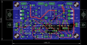
I made the change with diameter 13 mm and 5.08 lead space capacitor but I had to move a lot of things because I didn't want to increase the board size... I will post the new version later because I have to go now...
Rgds,
Marc
You are right, I didn't see that the electrolytic were 10.5 mm diameter instead of 12.5
I made the change with diameter 13 mm and 5.08 lead space capacitor but I had to move a lot of things because I didn't want to increase the board size... I will post the new version later because I have to go now...
Rgds,
Marc
Hi,
This is not a quasi complementary since it does not use a combination of MOSFET and Bipolar in the output stage
I have increased the size of the capacitors to 13 mm but I have to move a lot of things, however I have found that the 1 W resistor were far too big therefor I could reduce them During the modification I also modified some value based on the schematic drawn by DACZ (I hope that they are the last ones ?) and I found that the capacitor C7 had a wrong connection because the previous version didn't use a Zener diode ! By the way I have seen that it is possible to replace the Zener diode by a blue LED ? From my experience in tubes amplifier, it seems that LED are less noisier than Zener because they are used in the direct way and not reversed... What do you suggest ?
I have attached the schematic and the PCB for your comments.
Best regards,
Marc
This is not a quasi complementary since it does not use a combination of MOSFET and Bipolar in the output stage
I have increased the size of the capacitors to 13 mm but I have to move a lot of things, however I have found that the 1 W resistor were far too big therefor I could reduce them
During the modification I also modified some value based on the schematic drawn by DACZ (I hope that they are the last ones ?) and I found that the capacitor C7 had a wrong connection because the previous version didn't use a Zener diode ! By the way I have seen that it is possible to replace the Zener diode by a blue LED ? From my experience in tubes amplifier, it seems that LED are less noisier than Zener because they are used in the direct way and not reversed... What do you suggest ?I have attached the schematic and the PCB for your comments.
Best regards,
Marc
Attachments
.. it does not use a combination of MOSFET and Bipolar in the output stage
I
That is not the definition of a quasi complementary.
brian.
Some good info here:
Quasi Complementary Transistor Output | Radio-Electronics.Com
And here
How to identify a quasi-complementary amplifier?
Quasi Complementary Transistor Output | Radio-Electronics.Com
And here
How to identify a quasi-complementary amplifier?
OK, I understand, I also read that in the book of Bob Cordell, but his comments was that this approach was mainly due to the lack of good PNP power transistors in the past... But he say that it was not a very good solution and today real complementary output with PNP & NPN transistors offer much better performances, therefor my question : why we cannot use a PNP transistor like the MJW1302A in this amplifier ?
The fact that we are combining a MOSFET and a Bipolar could be interpreted as an Hybrid amplifier, like when we are using tubes and transistors
Marc
The fact that we are combining a MOSFET and a Bipolar could be interpreted as an Hybrid amplifier, like when we are using tubes and transistors
Marc
- Home
- Amplifiers
- Solid State
- Very simple quasi complimentary MOSFET amplifier