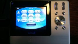
Today i performed first tests with my VcPre (i was a lazy builder this time) and i see some strange results:
- voltage on pot motor is low (i see some other builders are facing same issue). 4V without motor connected and 3.5V with motor running. Of course everything looks ok, motor is working slooow. I measure 6V before transistors.
There is other builder who can put the DMM and tell if he is measuring more than 4V on motor ?
- tried to adjust LDR's and i've obtained a maximum 5K on a LDR. Is that value ok, i don't know why i remember should be a bit more like 10k ??
-displayed attenuation looks strange and behave strange. I move the potentiometre and display shows same attenuation. Max att is -16db. In the movie posted by Wineds attenuation is displayed very nice. What to to to have the same behaviour ?
Thanks,
Adrian
Last edited:
Adrian, I have written a lot about the db-attenuation display already. There will never be a PIC firmware version that satisfies everybody, because there are too many factors
that have an effect on the display: the max. value of the 100K potentiometer, for example (my own one has a max. value of 85K), the max. value of the photo-resistor
of the LDR (normally it is between 7-8K), ...
Paul has another idea to build the attenuation lookup-table. Maybe it works.
As you know, I asked Uriah to provide the LDRs. I did not measure them on receipt, but as far as I remember, the typcial max. photo-resistance value of his LDRs is about 7-8K
(resulting in a "standard potentiometer" of 7-8K).
Your value of 5K is a little bit low indeed. Try to lower the MIC5205 output voltage by adding some small diodes into its output-voltage rail.
I found the schematic of the implemented motor H-bridge in this forum. It has been designed by FOTIOS. I LTSpiced the schematic and found a value of about +/- 4.2VDC.
My own VCPre shows values of about +/- 3.9VDC, but I am not scared about this, as long as the motor turns smoothly.
Do not take any NPN for the motor drivers; the transistor must be able to handle 100mA collector current. The 2N5551 will do this, the 2N2222 will do it, other small transistors
like BC548 "are on the edge".
Best regards - Rudi_Ratlos
That's fine Rudi, i can live without attenuation as long the attenuator is doing a good job.
Yesterday i increased the voltage into H bridge from 6 to 6,7V and on the motor i have the same voltage. The motor is moving but increasing a bit the voltage on it will speed up a little the operation.
So far is a great sounding attenuator and i owe you a big THANK YOU for it.
Regards,
Adrian
Yesterday i increased the voltage into H bridge from 6 to 6,7V and on the motor i have the same voltage. The motor is moving but increasing a bit the voltage on it will speed up a little the operation.
So far is a great sounding attenuator and i owe you a big THANK YOU for it.
Regards,
Adrian
Adrian
I am not familiar with Rudi's circuit although I have seen a simplified version of a small part of it.
One way to get higher maximum resistance from LDRs is to use a 100k trim pot as a shunt resistor. So you will tie two of the legs of the trimmer together. One of the legs is the wiper. Then you have only two legs and it is a variable resistor rather than a voltage divider. Take one of the legs of your new variable resistor and put it on the power going to the LED side of the LDR. Tie the other leg to ground. At 100k this will make a small difference. As you trim the value of your variable resistor smaller and smaller the max value of the LDR will increase and increase because you are taking a small amount of power away from it and the LED will not be as bright inside the LDR.
Uriah
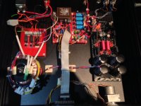
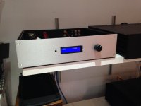
Photos of my Vcpre Gem.
Hi friends,
Here is my Vcpre. It is awesome. It has been partnered with the Pass DCB1 Hot-Rodded from Tea-Bag and was fantastic. As both modules do not have gain and my F5 and me needed some meat, I partnered it then with the Lukasz Fikus Lampizator in preamp mode and now I am fliying.
Well done Rudi...! Thank you...!
Regards,
Jorge
Attachments
Thanks!
It was conceived as Vcpre --> DCB1 but I needed more gain. Then now I switched to Vcpre ---> SRPP.
I showed photos of both configs...
Cheers!
Jorge
Very well done Jorge !
How is your configuration: DCB1>VcPre>SRPP ?
Adrian
It was conceived as Vcpre --> DCB1 but I needed more gain. Then now I switched to Vcpre ---> SRPP.
I showed photos of both configs...
Cheers!
Jorge
Hi friends,
Here is my Vcpre. It is awesome. It has been partnered with the Pass DCB1 Hot-Rodded from Tea-Bag and was fantastic. As both modules do not have gain and my F5 and me needed some meat, I partnered it then with the Lukasz Fikus Lampizator in preamp mode and now I am fliying.
Well done Rudi...! Thank you...!
Regards,
Jorge
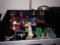
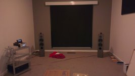
That's awesome Jorge! Very nice result. Finally started setting my system up again last week after home renovations. Initially I used a Squeezebox Touch into a Valab TDA1543 NOS DAC as the source. It sounded very good but a bit bass shy. Last night I setup my SACD player and the difference was astounding. Sweet music with all the clarity and transparency I had previously experienced using my manual DIY LDR attenuator. A sound so "naked" and untainted and vibrant. So thank you once again Rudi!
Looks like I know need to find a new DAC though as it looks like the passive IV stage in the Valab doesn't have low enough source impedance to work well with the VCPre.
Attachments
Last edited:
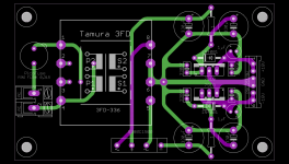
Bill, I will go and use the CALVIN - buffer. The CALVIN - buffer is an enhanced version of the JLH-buffer, and I like its schematic very much.
If you are in need of a PSU for it: I have just layouted a 115VAC/230VAC PSU for the CALVIN-buffer (see attached image).
Do you want some PCBs?
Best regards - Rudi_Ratlos
If you are in need of a PSU for it: I have just layouted a 115VAC/230VAC PSU for the CALVIN-buffer (see attached image).
Do you want some PCBs?
Best regards - Rudi_Ratlos
Attachments
Ivan, I will not be able to answer your question without any empathy.
Those, who are addicted to Nelson Pass' ClassA - amplifier designs, will prefer his B1 buffer.
I am not.
I have taken part in several "amplifier shootout - sessions", and my individual impression has been that ROENDER's FC-100 or a very well set-up SYMASYM show more liveliness,
details and stage than an AlephJ or F5 or .. does.
This is the only reason (missing sympathy for the B1) that I will go for the Calvin buffer (despite the fact that I have built a "quick-and-dirty" version of the original JLH-buffer
on a VERO-board - and it sounded very well in my ears).
I have not yet built the CALVIN-Buffer, since I am waiting for the (perfectly matched) input transistors, heatsinks, ...
Best regards - Rudi_Ratlos
Rudi,
I actualy bought an extra pair of Hensner's calvin buffers for that reason, funny I was looking around for a power supply this morning small enough to fit in the case with the VC pre. I will take you up on this one, but promise not to pester you about the parts.
Bill
I actualy bought an extra pair of Hensner's calvin buffers for that reason, funny I was looking around for a power supply this morning small enough to fit in the case with the VC pre. I will take you up on this one, but promise not to pester you about the parts.
Bill
Hi there!
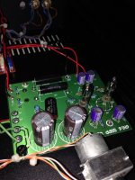
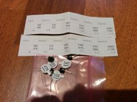
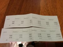
After long waiting I finally got all the electonic parts from reichelt. I read the emails and the instructions from rudi and there was mentioned a pair of the LDRs should be marked as "Series LDRs" and the other pair as " " .
But in the package of the mathced LDRs I do not have any pair marked as "Series LDRs" so I dont know which one to use as series and which one to use as shunt.
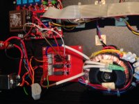
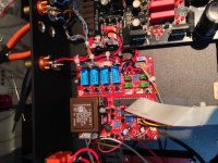
I attached 2 pics with the values measured. Could someone help me regarding this!? Don't want to do something wrong!!
Thank you in advance!
Greetings from germany
Ron
After long waiting I finally got all the electonic parts from reichelt. I read the emails and the instructions from rudi and there was mentioned a pair of the LDRs should be marked as "Series LDRs" and the other pair as " " .
But in the package of the mathced LDRs I do not have any pair marked as "Series LDRs" so I dont know which one to use as series and which one to use as shunt.
I attached 2 pics with the values measured. Could someone help me regarding this!? Don't want to do something wrong!!
Thank you in advance!
Greetings from germany
Ron
Attachments
- Status
- This old topic is closed. If you want to reopen this topic, contact a moderator using the "Report Post" button.
- Home
- Group Buys
- Versatile and comfortable passive pre-amp