The gain of the OPAMP is set up in a way that it gives the full swing from 0V - 5V on its output, which is the input to the PIC's A/D converter.
I first thought your max ADC input is 1.8V, now that you explained it, thank you.
This explains what I said in my post which is confusing you actually, not the audience. You mentioned that your differential OPAMP setup output changes from 0 to 5V which I assume is then supplied to PIC's ADC, and in your formula you are using a 1.8V to which I assume is the potential across the LED, right? 1.8V value is not valid when volume attenuation is at its max setting, because the voltage across the LED migh be 0, or near 0, what is the resultant gain of your differential OPAMP.
Are you sure that your differential OPAMP setup is able to output 0V (This is how it should work) when measuring the 1.8V (when volume attenuation is at its max setting) across the safety resistor? From the schematics that I have, when the pot is at its max attenuation, the voltage applied to the LDR LED is 0, or at least near 0.
I think this explains the sudden jump in your display from -50dB to -24dB.. This is when the LDR LED starts working and your differential OPAMP starts giving correct expected values according to your 1.8V potential across the LDR LED.
Correct me if I am wrong, I am not intending to confuse any body here, and this forum is for discussion.
regards
Last edited:
METAL, you are still wrong.
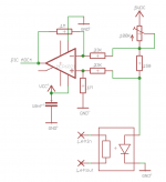
Find attached a simplistic image of the "dB - attenuation - display" schematic.
There is no (!) reference-voltage-input track in this scheme!
The reference-input voltage is only needed to manually calculate the attenuation!
When the wiper of the 100K potentiometer has a value of 80K (f.e.), some 41.2µA of current is flowing through the 150 Ohm safety-resistor, the voltage drop across this resistor
is multiplied by 30 (the gain of the MCP6021) and the MCP6021's output (which is input to the PIC) shows a resulting value of 2.43mV.
Calculate yourself please, if this is true!
When I change the potentiometer's wiper-value to 72K, the current increases to 45.7µA and the MCP6021's output shows a value of 2.46mV.
In summary: decreasing the value of the 100K - potentiometer by 8K from 80K to 72K increases the output-voltage of the MCP6021 by 0.03mV and this increase is much too small a value
compared with the internal resolution of the PIC's A/D converter, which is 5mV.
The PIC's ADC will not be aware of this change and keeps the dB_attenuation-value as it was.
This is exactly what Uriah has written: at high potentiometer values we are talking about a µA - increase of current that is flowing through the LED of the LDR,
when the potentiometer's wiper-value changes!
I can of course increase the gain of the MCP6021 (f.e. using 1M/10K - values for the MCP6021 - resistors, which will result in a gain of about 100),
but then its output swing ends (approaches 5VDC) at a potentiometer's value of about 10K! This is no option either!
Has my explanation been clear enough to make you understand, why the dB - attenuation is very coarse at high potentiometer values?
Best regards - Rudi_Ratlos
Attachments
Refer to my post Rudi, such small changes need smaller ADC reference, for example 1.1~2.5V ADC voltage reference. This will enable the ADC to detect values as small as 0.00108~0.00244V and help you solve your problem. You could have switched the ADC reference for very low values, and once the voltage from the diff. OPAMP is high enough (I mean higher than the small ADC voltage reference), you can switch back to 5V ADC reference and get very good results, another technique is to use a diff. ADC input, you may like to read more about it.
It is not about being wrong or right indeed, I am not trying to prove you are wrong, but showing you that there is always some way to improve what you have done with the volume display, and I don't see where I did any mistakes by giving some quick thoughts, I am just trying to think out of the box.
Please stop asking me behind scenes to "keep off this thread!" or "You do not seem to know what you are talking about.", there are moderators who can ban me if I did sth wrong. This forum is public and you can't prevent people from posting their opinions and thoughts. If you don't like my posts, you can simply ignore them.
If I did not know what I was talking about, I would not have written all these code lines, add to it I would not have told you to use the diff. OPAMP, slow down please..
regards,
Omar
Last edited:
Hello,
last night I replaced all the 2N5551s, but unfortunately to no avail. I tried different NPNs that I had lying around, but the voltage on the motor bridge did not rise above +/-3V. I also resoldered all the joints in that area....
I ran out of ideas, maybe someone can help out ?
?
Thanks, and best regards,
hallodeletue
last night I replaced all the 2N5551s, but unfortunately to no avail. I tried different NPNs that I had lying around, but the voltage on the motor bridge did not rise above +/-3V. I also resoldered all the joints in that area....
I ran out of ideas, maybe someone can help out
?Thanks, and best regards,
hallodeletue
Rudi, do you think this relay would work: V23105A5001A201 - TE CONNECTIVITY / AXICOM - LEITERPLATTENRELAIS,KONTAKT DPDT | Farnell Deutschland
As far as i see looks fine but i want your opinionalso.
Thanks !
As far as i see looks fine but i want your opinionalso.
Thanks !
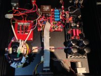
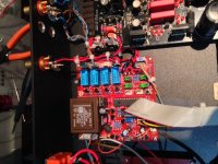
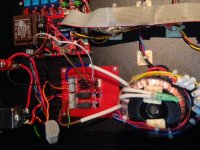
This is my VCPRE+HOTROD DCB1
Hi friends,
I have just finished the building of the vcpre plus a hotrodded dcb1 buffer. It works like a charm. I hope someday there is a workaround for the volume display but it is not that important, it is more asthetics than other thing.
On the other hand, I have a little doubt...when I press stanby, the dcb1 is switched off and the function works fine, but the display is allways on saying "standby". Could the display switched off also? Or stay few seconds on and then off ?
Best Regards,
Jorge
Attachments
Jorge: the display will not be switched off after entering the standby-mode.
But you can use the backlight function to dim the LCD.
Yoyoy: you can of course operate the potentiometer manually.
If you want a manually driven source selection, you need a 4:1 rotary encoder and run some wires to the solder-pads on the right side of the source-relay transistor drivers.
The solder-pads connect to the resistor in front of the bases of the driver transistors.
Best regards - Rudi
Some doubts more....
Hi Rudi,
Do the lifespam of the display is reduced due to be always on (although dimmed)? Also, energy waste side, is the power consumption low when in standby? I mean, which parts of the VcPre are on, everything or just some parts (display...)?
Best Regards,
Jorge
Jorge: the display will not be switched off after entering the standby-mode.
But you can use the backlight function to dim the LCD.
Yoyoy: you can of course operate the potentiometer manually.
If you want a manually driven source selection, you need a 4:1 rotary encoder and run some wires to the solder-pads on the right side of the source-relay transistor drivers.
The solder-pads connect to the resistor in front of the bases of the driver transistors.
Best regards - Rudi
so can i remove the pic uprocessor...? because it is not availble here, i am not used to in burnig PIC...
and im planning to use galvanized steel sheet as casing...
An externally hosted image should be here but it was not working when we last tested it.
regards
Yoyoy, I have definitely sent you the pre-programmed µProcessor along with the MCP6021 and the MIC5205 voltage regulator in a small, antistatic enclosure.
I am using the EAGLE CAD - software to layout the PCB.
I do neither distribute the EAGLE files nor do I distribute the µProcessor's firmware.
Best regards - Rudi_Ratlos
I am using the EAGLE CAD - software to layout the PCB.
I do neither distribute the EAGLE files nor do I distribute the µProcessor's firmware.
Best regards - Rudi_Ratlos
if im gonna revised and remove the uprocessor, this are the parts im not gonna need...
is there anything else?
An externally hosted image should be here but it was not working when we last tested it.
is there anything else?
- Status
- This old topic is closed. If you want to reopen this topic, contact a moderator using the "Report Post" button.
- Home
- Group Buys
- Versatile and comfortable passive pre-amp