Rudi, when the VcPre is in stand-by (by pressing power off from remote control) the LDR's are still powered on ?
Also i ask your advice about connecting the RCA ground connectors to the VcPre gnd. Would be ok to connect ground from every channel to a common point that goes to the VcPre pcb ?
Any advice in this grounding matter ?
After VcPre i intend to install a DCB1 buffer.
Where should i connect the metal case. Would be enough to connect using a film cap (Ac grounding) ?
Attachments
Last edited:
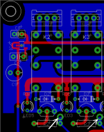
@Hallodeletue: look at the trough-hole pads above the base transistors controlling the relays! It is pricipally possible to connect
a rotary-switch to these pads and do the source-selection manually. The µProcessor's corresponding I/O pins must then not be
configured as output as they are currently. Maybe this is an option for a future firmware release.
@Adrian: the Standby-function does nothing else but switch on / off the leftmost black relay on your PCB (the currently offered PCB
does not have this relay, but has a direct interface to a "Soft-Power-On" - PCB).
So the LDRs will not be powered-off in "Amplifier-Standby-Mode".
Concerning your question about "common GND": I have done it exactly as you have proposed.
Best regards - Rudi_Ratlos
Attachments
Quite a good idea to switch off the LDRs when in standby ! Should be done in rev. 2.0. I take this is also the state when the muting relay mutes the output ? A small delay in switching the LDRs on would be good when the VCPre is switched back on again. I am not fully aware of the schematic but I think this is a nice enhancement.
Last edited:
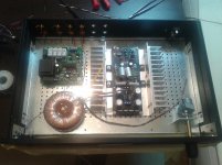
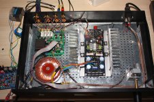
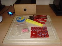
I didn't notice a grounding scheme. It appears you have a floating gnd, and keeping the signal and gnds together in their respective domains. Yes? But, no hum? That's a good thing.Finished building of preamp (VcPre+DCB1), small adjusments following days regarding cable management, dead quiet so far.
Also FC-100 in the pictures.

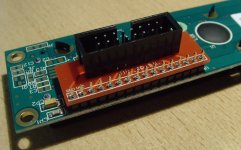
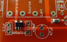
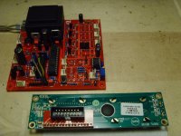
Gentlemen, in the meantime I have received the PCBs, and my German DIY-friend Peter has already cut the auxiliary PCB.
The second image shows, how to solder the DIP-to-SIP adapter.
Uriah's matched LDRs arrived in Germany, but are currently delayed by German tax authorities.
I need to wait for my own VCPre-PCB. You remember: I asked a friendly DIYer to solder the SMD-components for me.
As soon as I have it back, I will solder it and do a final hard- and software test.
I am confident that I will able to dispatch your letters in the course of next week.
Best regards - Rudi_Ratlos
Attachments
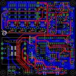
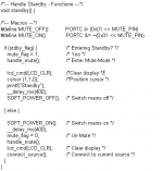
Jean-Paul: this (switching on / off the LDRs - in effect: switching on / off their power supply in case of STANDBY or MUTE)
can be done easily, but must assure that hard- and software work together happily!
Have a look at the two attached pictures.
The MIC5205 - Enable pin is connected to the PIC µProcessor's MUTE pin (highlighted by the white track).
Both pins (MIC5205- Enable- and PIC16F886 - MUTE - pin) adhere to standard CMOS operation.
The "Mute-Command" will drive a "0" on the PIC's output pin; the "Un-Mute - command" will drive its output to "1".
And Soft-Power On / Off does of course make use of the MUTE - function (to prevent a "Klack" on the output").
So: congratulation! You have just entered the digital audio world!
Best regards - Rudi_Ratlos
P.S.: I will try and implement / verify this feature on the round#2 - PCBs, maybe in August, after some thorough tests!
Attachments
Last edited:
Adrian, the current VCPre - layout and software does not support the "Mute LDR" feature.
I will check, if this feature can be implemented, once I have assembled my PCB. If possible (for example: does the µProcessor
meet the voltage levels needed to enable / disable the power supply (MIC5205) for the LDRs?) and the needed software-changes are not serious,
I will think about implementing this feature in a future VCPre - version.
Best regards - Rudi_Ratlos
Gentlemen: I have told you about my fear soldering the VCPre - SMD-components some time ago and asked a DIY-friend to do it for me.
Since I did not receive a feedback from him until today (maybe I have misspelt his home-address?), I tried and did it myself today.
You have given me several recommendations, how to do it, but left out the two most significant ones:
"Have a big cigar and 1-3 whiskys before you start soldering and clap your hands on your shoulders and tell yourself:
"You will do it!".
This is the result! Beautiful, isn't it?
Best regards - Rudi_Ratlos
Attachments
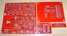
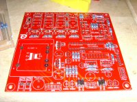
Gentlemen: start and solder the low-profile components (SMD, diodes and resistors) first (pictures 1 and 2).
This will take no more than an hour.
Then have a rest!
To solder the diodes and resistors has been a real pleasure to my old eyes (and cannot be compared to the SMD - components,
which have been a real challenge)
... to be continued ...
Best regards - Rudi_Ratlos
This will take no more than an hour.
Then have a rest!
To solder the diodes and resistors has been a real pleasure to my old eyes (and cannot be compared to the SMD - components,
which have been a real challenge
)... to be continued ...
Best regards - Rudi_Ratlos
Attachments
Gentlemen, I continued the build of my VCPre last night and soldered everything but the relays and LDRs.
I inserted a pre-programmed µProcessor and powered on: everything works as designed.
Take care when you solder the Tantalum capacitor on the output of the MIC5205! This is a polarized capacitor!
I will go on and solder the auxiliary PCBs and connectors / connections this afternoon and will begin with the final software-test then.
Best regards - Rudi_Ratlos
Attachments
- Status
- This old topic is closed. If you want to reopen this topic, contact a moderator using the "Report Post" button.
- Home
- Group Buys
- Versatile and comfortable passive pre-amp