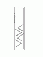
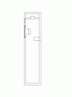
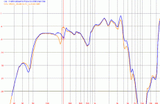
Zozo said:The internal dimensions of the box I experimented with (in meter) : 0.97H x 0.2W x 0.17D.
I attach here two layouts wich worked the best for me. The first is rather a TL like approach, while the second is a combination of the TL and Helmholtz chambers. Both can reduce the spike, but also the Q of the vent, therefore I think it is important to tune the chamber(s) exactly to the frequency of the standing wave as you and others already pointed out.
Very interesting approach Zozo. Can you be sure that the second is a TL + Helmholtz and not just TL?
What sort of damping did you use in the line?
It strikes me that these are similar to the Daline approach (also used in the Seventh Veil 'System IV') with two differences:
1. You have a port instead of a box
2. Your line is closed rather than open.
Do you know the length of the line, relative to the resonant frequency of the driver? Is it 1/4?
It's amazing how many possibilities there are.
Steve
7V,
I didn't calculated the length of the line, because didn't think it is important. The main goal with the second design was to create 'traps' to the air. These chambers are quite similar to Helmholtz resonators, but presumably with much smaller Q.
I have used dacron damping with both approach.
Zozo
I didn't calculated the length of the line, because didn't think it is important. The main goal with the second design was to create 'traps' to the air. These chambers are quite similar to Helmholtz resonators, but presumably with much smaller Q.
I have used dacron damping with both approach.
Zozo
Zozo:
Thank you for posting those drawings. We now know that the enclosure that belongs to the response graph was very tall and skinny, just like the Pioneer.
One more question. You said that the response came from an enclosure that had no stuffing.
My question is: is the response graph for an empty box without any dividers or plates?
Or was the response graph for an unstuffed box but which had those dividers or plates in them?
The reason I ask is that your "spike" seems to be of considerably less amplitude than the Pioneer "spike". We now know that both enclosures were tall and skinny. I am wondering if the considerably reduced amplitude of your "spike" was due to the fact that the dividers you put in the enclosure cut it down quite a bit.
kelticwizard said:
A) Is the volume of the internal [wavelength] resonator subtracted from the total volume of the enclosure?
Originally posted by 7V:
Yes, I'm sure it is.
Perhaps not. When Helmhotz resonators go below their tuning frequency, they quickly become like a dipole-that is, they rapidly begin to act as if they were mounted on a single board and there was no enclosure around them.
For instance, the double chamber reflex by George Augspurger has a Helmholtz resonator-granted, one that is vented to the outside as well as back into the bigger chamber-that occupies no space at the bass frequencies. The F3 cutoff is identical to a vented box of identical volume that has no Helmholtz resonator in it.
http://www.diyaudio.com/forums/show...page=15&highlight=double chamber&pagenumber=1
Very possibly, quarter wave resonators act the same way. That is, once they hit a certain frequency, they stop acting like enclosures and "open up". If quarter wave resonators act the same as Helmholtz resonators in this way, then their volume would not be subtracted from the box in the bass frequencies.
There is no need to care if the resonator volume is subtracted from the total box volume above the bass frequencies. the woofer needs very little box volume to play 150 Hz on up.
I do not know if quarter wavelength dipoles act like Helmholtz resonators in this regard. I just think it is possible that they might.
kelticwizard said:Very possibly, quarter wave resonators act the same way. That is, once they hit a certain frequency, they stop acting like enclosures and "open up". If quarter wave resonators act the same as Helmholtz resonators in this way, then their volume would not be subtracted from the box in the bass frequencies.
Excellent (and quite possibly right!).
If so, the volume of the resonator is "free". What about the frequency of the standing wave?
Suppose we use the "bottom segment of the cabinet becomes a Helmholtz Resonator" idea (as opposed to a tube). Do we:
(a) ignore this segment when calculating the frequency
(b) calculate assuming that the sound is now reflected by the top of the Helmholtz Resonator segment
(c) a bit of both?
Steve
kelticwizard said:Zozo:
One more question. You said that the response came from an enclosure that had no stuffing.
My question is: is the response graph for an empty box without any dividers or plates?
Or was the response graph for an unstuffed box but which had those dividers or plates in them?
The response graph belongs to a completely empty cabinet. No braces, no plates or whatsoever.
Zozo
Zozo:
Thank you for the explanation.
I seem to remember the Pioneer frequency response chart-the Pioneer was 48" internal height-as having a "spike" of much greater amplitude. Like 8 or 10 dB each direction. and that was with an inch of stuffing on the internal walls.
Yet your unstuffed pipe, a little shorter but of very similar proportions, shows a "spike" of about 3 dB each way.
Once again, the mystery deepens. Or once again, my memory fails. One or the other.
kelticwizard said:I seem to remember the Pioneer frequency response chart-the Pioneer was 48" internal height-as having a "spike" of much greater amplitude. Like 8 or 10 dB each direction. and that was with an inch of stuffing on the internal walls.
An inch of damping is going to be negligble at the frequency of interest.
dave
Planet 10:
Yes, you are right. I have an article here that states that most stuffing, at the amounts commonly used, (one inch around), is ineffective below 500 Hz. It's effectiveness rises with frequency. At 140 Hz, there would be no difference between a stuffed and unstuffed pipe.
Hmmm, what was I thinking?
Yes, you are right. I have an article here that states that most stuffing, at the amounts commonly used, (one inch around), is ineffective below 500 Hz. It's effectiveness rises with frequency. At 140 Hz, there would be no difference between a stuffed and unstuffed pipe.
Hmmm, what was I thinking?

7V said:
What about the frequency of the standing wave?
Suppose we use the "bottom segment of the cabinet becomes a Helmholtz Resonator" idea (as opposed to a tube). Do we:
(a) ignore this segment when calculating the frequency
(b) calculate assuming that the sound is now reflected by the top of the Helmholtz Resonator segment
(c) a bit of both?
Steve
7V:
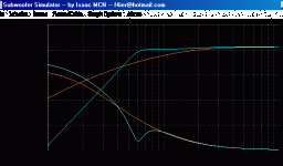
First, I would like to chart the frequency response chart for a woofer in both a well designed vented box and an enormous, (600 L) sealed box. The sealed box of over 20 cu ft is meant to simulate an infinitely long and infinitely high wall.
The speaker is 8 ohms. The drive level is 50 watts, (20 volts).
Qts = 0.38
Fs = 30 Hz
Vas = 56 Hz.
The orange is the speaker in an infinite baffle, (600 L).
The light blue is the speaker in a vented box of 56 L and tuned to 30 Hz.
The only difference between the infinite baffle and the dipole is that the bass is better because the bass cannot wrap around the baffle and cancel the front wave. If the speaker were unenclosed, the bass would have a worse rolloff that started sooner from that effect.
Notice that even though the Closed Box-of which the Infinite Baffle is a variant, has approximately the same cone excursion as the Vented Box. Yet the Vented Box has a reputation for driving the speaker into wild cone excursions.
The reason is that if we had the speaker unenclosed and kept adding more power to it at, say 20 Hz, the speaker's excursion would get gradually larger right before our eyes. the large excursions come as no surprise, since it is a linear result of added power.
The Vented Box tightly controls the cone excursion right down to the tuned frequency. Then, suddenly, it lets the speaker go and revert to it's unenclosed behavior.
It looks like the cone is spinning wildly out of control. It is no more out of control than than an unenclosed speaker. It is just that when the Vented Box goes below it's tuned frequency, it "goes dipole" real quick, and it looks like it is going crazy.
The rise in cone excursion is a measure of how fast a Vented Box-a Helmholtz Resonator-"goes dipole" once it passes the tuned frequency.
By the way, the excellent freeware program I used to illustrate this is Subwoofer Simulator by our own F4ier, downloadable at the following URL:
http://www.geocities.com/f4ier/speaker.htm
It simulates many boxes and charts impedance, impedance phase, and about a dozen other things.
Attachments
Now, the reason for all this is to illustrate that above the tuning frequency, the air does not escape from the box. If it did, the Vented Box would resemble a dipole at all frequencies, and it would be essentially useless as an enclosure.
The Vented Box goes through three phases.
Phase 1: From the highest frequencies down to an octave or so above the Helmhotz tuning frequency, it is identical to a Closed Box.
Phase 2: From an octave above the tunig frequency, (Fb), down to the tuning frequency, it is a Phase Inverter. It reversed the phase 180°. If it did not do that, the output from the back of the speaker would come through the vent and cancel the output from the front of the speaker. Instead, the output from the back of the speaker gets it's phase inverted, and reinforces the output from the front. In fact, at Fb, the output from the vent, (which is completely generated from the back of the speaker cone), is four times the output from the front of the cone!
All that is due to phase inversion in the octave directly above the tuning frequency.
Phase 3: For frequencies beneath the tuning frequency, the Vented Box reverts to a dipole, as the cone excursion graph shows. The now-uninverted back waves leak through the vent to cancel the front waves, as if the enclosure did not exist.
7V:
So what your question is, suppose put the woofer near the top of a small skinny enclosure, and the vent just below the woofer. Then we take the bottom half of the box and turn it into a Helmhotz resonator tuned to the frequency of the standing wave of an undivided box.
What you want to know is, if the frequency of the standing wave of the undivided box is 140 Hz, wouldn't that frequency go up now that the box length is effectively cut in half?
Should we now tune the box to 280 Hz instead of 140 Hz?
My guess is: no.
Because if we tune the box to 280 Hz, then below 280 the Helmholtz resonator becomes a dipole. That 140 Hz standing wave will not "see" a divided box-he will see an undivided box. The dividing action of the Helmholtz resonator ceases quickly below the tuning frequency. Below 280 Hz, the resonator becomes nonexistent, just as the Vented Box became nonexistent below the Fb of 30 Hz in the example above.
Therefore, we must tune to or slightly below the frequency of the standing wave in the undivided box.
What the proportion of the box volume is, compared to total box volume, is open to question. But whatever the volume turns out to be, it has to be tuned to 140 Hz in a 46" enclosure. That is the frequency of the standing wave in an undivided box.
Ok kelticwizard, that makes sense (took a little time to get there but ...). You're saying, I think, that below the resonant frequency of the HR, it doesn't really exist and that this applies to the cabinet standing wave frequency as well as cabinet volume.
So, let me ask Zozo a question. Let's go back to this ...
Zozo, in view of postings on this thread, this other Helmholtz resonator could be exactly what we're looking for. With your two chamber setup did you attempt to tune the 2nd chamber to the standing wave frequency of the (whole) cabinet or were you aiming for something else at this time?
Also, do you still have those nearfield measurements lying around somewhere to show us (together with the speaker dimensions) or could you describe the measurements in more detail?
Steve
So, let me ask Zozo a question. Let's go back to this ...
Zozo said:I have also tried the two chamber setup, but this way you actually create another Helmholtz resonator which sucks energy from the other one. This was clearly seen from the nearfield measurements.
Zozo, in view of postings on this thread, this other Helmholtz resonator could be exactly what we're looking for. With your two chamber setup did you attempt to tune the 2nd chamber to the standing wave frequency of the (whole) cabinet or were you aiming for something else at this time?
Also, do you still have those nearfield measurements lying around somewhere to show us (together with the speaker dimensions) or could you describe the measurements in more detail?
Steve
It was nice to speak with you on the phone yesterday, kelticwizard. It's good to be able to put a voice to the text.
It occurs to me that, since the Helmholtz Resonator section is "invisible" as far as the low frequencies are concerned, nothing would be gained by having the top of this section at an angle.
Just a thought.
Steve
It occurs to me that, since the Helmholtz Resonator section is "invisible" as far as the low frequencies are concerned, nothing would be gained by having the top of this section at an angle.
Just a thought.
Steve
7V said:So, let me ask Zozo a question. Let's go back to this ...
Zozo, in view of postings on this thread, this other Helmholtz resonator could be exactly what we're looking for. With your two chamber setup did you attempt to tune the 2nd chamber to the standing wave frequency of the (whole) cabinet or were you aiming for something else at this time?
Also, do you still have those nearfield measurements lying around somewhere to show us (together with the speaker dimensions) or could you describe the measurements in more detail?
Steve
When I played around with the two chamber setup I didn't pay attention to calculations, because I wanted quick results and also had several other options in mind like the TL like setup and others. Nevertheless here are the measurements.
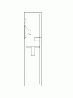
I have divided up the enclosure at around the half and first put a 14cm long tube inside then a much longer one, about 1m. I still have the folded tube, so I can make a measurement on the length if it is important.
So, the enclosure :
Attachments
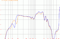
... and here are my measurements. These are a little bit different from the first one I posted and this is because I didn't use XO with these ones, so just the woofer alone.
The blue curve belongs to the longer tube as you might guess out. There is no sign of standing waves (at least no spike), but the woofer starts to roll-off much earlier.
I was thinking of using longer tubes (around 2-3m) to extend the rolloff frequency, but finally started to try other options.
I think the problem with this setup is that the tuning frequency gets higher as the woofer doesn't see the whole enclosure behind, only the half of it.
Zozo
Attachments
I have good news Gents after the discouraging ones, short of proof of concept ! The idea with the resonator chamber really works 
When I experimented with design previously shown I had a different approach and was not thinking exactly on the effect of a Helmholtz chamber. Finally it is one, but was tuned to much lower frequency than neccesary to have the spike cancellation or supression effect.
In order to have a resonant chamber around 180-200Hz you do not need a large box, so 3-4 litres sufficent instead of 20. I have used ETF 5.x to calculate the initial values (volume and tube length primarily) then built one in my experimenting box as it shown on the picture bellow :
Attachments
...and as usual here are the measurements. The orange curve is with the closed chamber and the blue is with the tube's mouth open. The tube length is really short about 5-6cm (need some fine tuning to get the exact frequency). I have used some damping in the chamber to reduce the ripple, but it doesn't yet seem to be enough.
So what do you think ?
So what do you think ?
Attachments
- Status
- This old topic is closed. If you want to reopen this topic, contact a moderator using the "Report Post" button.
- Home
- Loudspeakers
- Multi-Way
- Vented Divider To Cure Standing Waves In A Tall, Narrow Enclosure?
