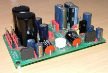
Good looking board!
I hope it will work good ...
My suggestion: put some isolation tube around the wires from the coupling caps, so they cannot touch the needed heathsink for the LM3875 chips.
BTW: I really regret what happened to Zang, digi01, in the last days.
For me, Zang is not a copycat, but an idealist, a hobbyist like most of us are. I hope, we can read new postings from Zang here in this forum in the future!
Greetings to China and to the Gainclone World!
Franz
P.S.
Zang: the electrolytic element has to be avoided! Dont combine some metals/alloys, producing together an galvanic element, as it will destroy the material over time.
Good looking board! I hope it will work good ...
Thanks Franz, I'm hoping the same.
My suggestion: put some isolation tube around the wires from the coupling caps, so they cannot touch the needed heathsink from the LM3875 chips.
Good tip!
BTW: I really regret what happened to Zang, digi01, in the last days.
Did I mis something? What happened with Zang?

Regards
Banned
Joined 2002
GeWa said:
Thanks Franz, I'm hoping the same.
Good tip!
Did I mis something? What happened with Zang?
Regards
To be honest and say the truth he left diyaudio because of PD. He said he will be on looking around and stuff but hardly will be on any more.
He is away from home for a week on vacation at this moment tho.
Did I mis something? What happened with Zang?
You may have a look here:
http://www.diyaudio.com/forums/showthread.php?s=&threadid=78288
I am an optimist and I hope, to find in the future postings from Zang here!
Kind regards
Franz
P.S.
Dont forget: we are all copying A commercial amp, so my comment about copycats is strange! Isn't it?
Thanks for the link Franz. I've just read the thread and what is there to say..... I promised myself when I signed up at this forum not to take part in those kind of discussions because they all end up in the same way. As you say, we all are copying from one another so there is no reason to calling the kettle black. I for one hope that Zang keep's on posting and helping us out with boards for our projects.
Regards
Regards
Franz G said:
You may have a look here:
http://www.diyaudio.com/forums/showthread.php?s=&threadid=78288
I am an optimist and I hope, to find in the future postings from Zang here!
Kind regards
Franz
P.S.
Dont forget: we are all copying A commercial amp, so my comment about copycats is strange! Isn't it?
Oh my lord.... Zand is offering cases. Not kits, not amps... Just metal boxes. He PLAINLY states that the internals need to be purchased seperately.
Thats' all I have to say about that... (Forest Gump)
No exotic components needed Loek, i have the tube for you for free (E88CC),. I build the earlyer version from Zang and Franz, with the boards with some bugs that had to be fixed. I love the sound and i am playing with this amp since he was ready. Very, very good. My friends do not beleve there eyes when they see the very tiny and little design.
Till later on Loek....
Till later on Loek....
I could not agree more to Wim.
This tiny tiny amp sounds really well!
I moved to a new place where the soundstage is even wider. The only problem is that I have a nasty room resonance at 35Hz
I finished the amp as soon as I possible, tried to swap some tubes, but could not here any difference.
I use it ever since. My bosoz-X pre and Aleph 30 are sitting in 'de berging' collecting dust. Especially with this heat going on at the moment this is a very nice amp to have. The tube also does not need a lot of time to warm up. It is really silent and hisses only a little bit out of my 92dB speakers. No hum at all.
I have 2 sets of the old boards that I do not have time to debug so I am certainly intrested in the new PCB so I can make a desk amp.
PLEASE have some made! Please.......... Pretty please.... With sugar on top. Maybe a little cream and a cute girl to serve it... and umm, well I guess I better stop now before the forum police come get me..
PLEASE have some made! Please.......... Pretty please.... With sugar on top. Maybe a little cream and a cute girl to serve it... and umm, well I guess I better stop now before the forum police come get me..
I'm sorry; I've been divorced now for six months... Seems my sense of good taste has been eroded some what...
Anyway, I would really like a set of boards so I can mke a small desk amp. And if the case it was designed to fit in is an option I love to get 2 of those too. I don't know if they will be available here in the US.
I would really like to replace this crappy set of headphones I use at work with a real system...
Hi guys
Hhmm, a busy day today at this dusty thread. To give you an update: I haven't finished the amp yet, only yesterday I received the small Omron relay. At this point I still need the tube and the heatsink (which has to be customized for my needs). I'm still in doubt whether I'm going to install the T-Network components or not.
As far as it goes for "bugs", well there are a few. The small heater supply groundplane isn't according to my layout (it has only the outline). I also made a small mistake with the diameter of the electrolytic caps next to the LM chips, they still fit but it's all a bit tighter than planned. For the rest, I'll let you know when I fire up the thing.
I don't know how many boards Zang has have made but if you want I can check with him. I'm not sure how quick he will respond because in his last email he told me that he was getting married!?
Also the question was raised if there were any exotic parts needed; Answer: NO, al the stuff you need for this board is commonly available. The two things that could be a bit more difficult to obtain are the correct tube socket and the small relay. I have a parts list but I can't resize it enough to post it here. So for those who want it, let me know and I will email it straight away.
Regards
Attachments
Hi Wim
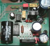
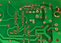
Wel there is actually nothing to fix. What should have been a small groundplane ended up as an outline only. The Gerber files I have sent to digi01 were correct so something happened during the manufacturing process, but as I said nothing to worry about. If one really wants than the soldermask can be carefully scraped away in that area, stick on a small piece of copperfoil and soldered around the edges. (a bit far fetched if you ask me)
Another detail is that R104 has to be soldered on the copper side.
The attached picture shows it all.
I will mail you the BOM right away.
Regards
Attachments
- Status
- This old topic is closed. If you want to reopen this topic, contact a moderator using the "Report Post" button.
- Home
- Amplifiers
- Chip Amps
- VBITNGC building & comment