I'm not! I'm a chemist!dshortt9 said:Hey! Use duck tape! What kind of an engineer are you?

And besides, Duct tape is a valid permanent solution as far as I am concerned! If you want to do it half (not sure if I can post that word)'ed use scotch tape. Duct tape is the real deal!!!!
Cap coupling
Hi,
The art work shows an axial footprint for Cin. When I look at the picture closely, Cin1a and Cin2a are actually not populated and Cin1b is shorted by jumper. Looks like the FC in BOM is a decoy afterall and they have gone direct coupled.
Actually I unplugged the coupling caps on my opti-mos (don't tell Randy) without any crisis. And there is no servo to block dc in my preamp. Would anyone willing to give it a try on the 4702? That would free a lot of board space and I can go single layer.
I'm also thinking about separate power supplies to the 4702 and the driver stage. Say regulated 30V to 4702 and unregulated 55-60V to the driver stage. Then you definately don't need a heat sink for the 4702. Will it work?
Cheers,
KK
As long as your signal doesn't have DC offset you should be fine shorting your input caps or leaving them out. I shorted my input caps and it worked well for me on my test bench, and I can't for the life of me figure out why I would want to keep them in.
As for the heat sink, National says no. We have pretty much agreed it is not absolutely necessiary, but a simple TO-220 heat sink would be prudent. If there is no sink, the chip will probably run a little hot, and there really isn't a great reason not to have a small heat sink on the chip.
As for the separate power supplies, I have thought about this as well, but I don't have a good answer for how it will work. Something that is a little telling is that the National guys didn't use a regulated supply for the chip on their amp. This doesn't mean it won't help, but with the other chipamps there hasn't been too much of a need for regulation.

Driver
Hi dfdye,
Point taken about the PS. Now for something completely different...
I'm looking at the L-mosfet pair 2SK1508 and 2SJ162 for the driver stage. Any comments?
I'm working in the office too, but this is Saturday noon in HK.
So forgive me if I distract you some more (but you seem to like distraction).
Cheers,
KK
Remember, you can use the boards you got with no input caps. You can jumper either the Cin or CinB holes to make a direct path to the input resistors. I personally will be using the CinB holes since it will make a straighter path, but that's just me being OCD.
HOWEVER!!! I would NOT leave off Ci!!! You can even beef that up to drop the highpass feedback filter cutoff. I think the National guys used a 200uf electrolytic, but that can be a 16V cap and you should bypass that with a good film cap.
HOWEVER!!! I would NOT leave off Ci!!! You can even beef that up to drop the highpass feedback filter cutoff. I think the National guys used a 200uf electrolytic, but that can be a 16V cap and you should bypass that with a good film cap.
Re: Driver
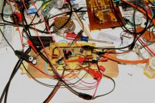
Actually, the avitar picture I have is one taken by me in my lab during one of these late night "distraction" sessions, but I think my experiment is done, so time for bed.
David
I have stayed away from mosfets mostly because I am used to working with bipolars, so I don't really feel comfortable commenting. I'll leave that to somebody else to figure out!kkchunghk said:I'm looking at the L-mosfet pair 2SK1508 and 2SJ162 for the driver stage. Any comments?
Yea, I am in the middle of a photolysis experiment. Shoot the laser for 2 hours and take a spectrum. Repeat X times until you don't see any more change. Really fun stuff, let me tell you!!!! And it is midnight here in the Eastern Time Zone in the States.I'm working in the office too, but this is Saturday noon in HK.
So forgive me if I distract you some more (but you seem to like distraction).
Cheers,
KK
Actually, the avitar picture I have is one taken by me in my lab during one of these late night "distraction" sessions, but I think my experiment is done, so time for bed.
David
kkchunghk:
If you want to use lateral mosfets I would use the 2sk216 and 2sj79 for drivers as they have much less input capacitance than the ones you mentioned. They were designed to be drivers. Look under components - vintage for data sheets at this link.
http://www.ampslab.com/index.html
I have a pair of them driving 3 pair of 2SK1508 and 2SJ162 in an amp playing as I type.
Darlingtons are by far the simplest solution for an output stage. Any output stage of your choosing should be fine as long as the "total Hfe" is enough to drive your load without taxing the transistors too much. I have been playing with a few different configurations, but if you are simply looking to get this running and don't want to get fancy, (and have it sound pretty good in the process) darlingtons are your best bet.
David
David
Darlington outputs using the Sanken SAP16N/SAP16P darlington pairs looks to be especially easy (see jackinnj's post earlier in this thread). I am sitting on a stash of TIP142/TIP147 darlington pairs leftover from another project. I'll take a look at using those for outputs.
OK -- here are some very preliminary results of the LM4702 + Sanken SAP16 diode incorporated transistor amp following National's application note AN1490 and some twiddling -- THD+N 0.028% -- this with a supply which is running at about 1/2 the voltage recommended by National -- the hotter you run the transistors (|Vcc| + |Vee|)^2 the lower the THD. Conclusion -- the National numbers (THD+N < 0.001%) are within reach for a DIY amp. This is really exciting.
Attachments
Nice work Jackinnj! SAPs seems to be promising
I burnt my LM4702 an hour ago - doesn't like shortcut do GND
I burnt my LM4702 an hour ago - doesn't like shortcut do GND
An externally hosted image should be here but it was not working when we last tested it.
Really, you didn't even read three posts up?Carl_Huff said:Progress report anyone??
Who has built an amp around LM4702 that is willing to share their experience? What output devices did you use?
I think either you have missed what everyone has done or you aren't asking a specific enough question. I have been moving (and I am a slacker) so I haven't finished my CFP output stage, but there are already several options (MOSFETs, Darlingtons) in play.
- Status
- This old topic is closed. If you want to reopen this topic, contact a moderator using the "Report Post" button.
- Home
- Amplifiers
- Chip Amps
- Vbe Multiplier for LM4702 Output Stage