Hi Merlin . Thats all I have , the rectifier has AC heaters and the rest are DC . You have to lift all the heaters to keep within tube specs . The output changed to single 10 ohm and 2 x 47 mf caps see the picture . the whole design is a standard schematic that i adjusted to suit tubes and parts used . I am just a hobbyist and I leave the real work to people like Salas .
Interesting how you placed the ribbon tweeter's wider dispersion side of polar pattern. Should be blending better in the vertical direction with the wide projecting mid dome. Needs stricter aim to your listening position vs usual speakers regarding horizontal HF dispersion though?Have a few English 6AV6 which are very sensitive to microphonics . Rest of system is Pre amp Ming Da MC 2A3 with some minor cap changes and tube rolling , power amps are Transcendent OTL for mid and high and local made CYMER kt88 push pull mono blocks for the base . The speakers I have are rebuilt Yamaha NS1200 , base cones from NS1000 x which are carbon , original dome mid and a large Fountec ribbon for the tweeter . crossovers were rebuilt with large solen air core and caps . 2 dacs that are tube output and custom DIY built .
Yes , the position was really about getting it to fit I used the original tweeter hole and only made it larger to accommodate the ribbon this was about 15 years ago . The original speaker was not in the units when i purchased . The ribbon was a huge step up in calming the highs , The speakers sit on small stands and are great for the listening lounge but yes they are stricter on the sweet spot than normal .
Two benefits that I know of . The heaters can be switched on first , then the high voltage secondary, prolonging tube life. The second benefit would be reducing rectifier noise between the high voltage secondary and the filament secondary.Hello,
I`m just planning an Itch build an am just before ordering the power tx.
Are there any listenable benefits by separating the heaters form the hv secondaries. Or will be one transformer be sufficient for all?
Best
Rents
Salas, is it possible to substitute 6N6P for 6SN7?
It seems plausible given that the "top" half of the 6SN7 is operating with 110V on the anode, which is just fine for the 6N6P. I think that we would be looking at a much higher current draw with the 6N6P, maybe something like 18mA, which would help drop the voltage to the levels indicated in the schematic for the 6SN7. Maybe R10 could be lowered substantially? The role of the valve's plate resistance in this situation is confusing to me, to be honest, and limits my ability to do the calculations myself.
It seems plausible given that the "top" half of the 6SN7 is operating with 110V on the anode, which is just fine for the 6N6P. I think that we would be looking at a much higher current draw with the 6N6P, maybe something like 18mA, which would help drop the voltage to the levels indicated in the schematic for the 6SN7. Maybe R10 could be lowered substantially? The role of the valve's plate resistance in this situation is confusing to me, to be honest, and limits my ability to do the calculations myself.
Yes you can substitute the 6SN7 with noval. Better avoid 6N6P because not as linear IMHO. I had suggested the 6DJ8/6922/ECC88/6N23P for that in the past. Have seen that done successfully here before and once in another forum too. Will not sound exactly like with the 6SN7. Since they had also posted detailed impressions you can more or less understand what to expect when combining those types I suggested.
You don't have to change something in the Rev1.2 schematic. 6922 or equivalent will drop right in for 7mA Ip and about 105V across each section.
You don't have to change something in the Rev1.2 schematic. 6922 or equivalent will drop right in for 7mA Ip and about 105V across each section.

Thanks for the reply!Yes you can substitute the 6SN7 with noval. Better avoid 6N6P because not as linear IMHO. I had suggested the 6DJ8/6922/ECC88/6N23P for that in the past. Have seen that done successfully here before and once in another forum too. Will not sound exactly like with the 6SN7. Since they had also posted detailed impressions you can more or less understand what to expect when combining those types I suggested.
You don't have to change something in the Rev1.2 schematic. 6922 or equivalent will drop right in for 7mA Ip and about 105V across each section.
You are welcome. We will be happy to see your build here if you will proceed.Thanks for the reply!
Keep in mind that the Valve Itch also performs nicely without MC/LMC SUT avoiding much cost. Suitable for HMC type cartridges direct connection like Denon DL-110 Dynavector DV-10X5 etc.
Has low enough noise and high enough gain on its own for that.
(No less than 43dB with 6SN7 in 2nd stage, no less than 46dB with 6922 in 2nd stage. Exact figure depending on both stages valves mu tolerance).
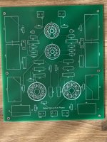
Another valve itch finished. Total gain about 56dB with Partridge transformers.
Extremely quiet for a tube phono. Very nice, detailed and warm sound. I have also ordered some Sowters input transformers, which should give me more gain and of course reduce hiss even more. Not as high resolution as my UFSP but close. Very addictive listening to it!
Extremely quiet for a tube phono. Very nice, detailed and warm sound. I have also ordered some Sowters input transformers, which should give me more gain and of course reduce hiss even more. Not as high resolution as my UFSP but close. Very addictive listening to it!
Attachments
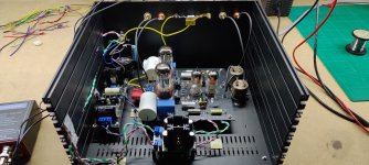
Hi Felipe, tubes are Tungsol 6SN7 for the exit and for the input some matched 6N2PEV. I used FFT (quantasylum Q401) to get better gain match between channels and lower THD, by swapping various tubes. Also helped a lot with grounding.
As cart I use my trusted AT Art9.
As cart I use my trusted AT Art9.
- Home
- Source & Line
- Analogue Source
- Valve Itch phono