There will be many capacitor types to test. One very good interstage will be K72 0.047u 500V Teflon also. And other types for the Riaa as well as small value changes from 0.015-0.0155u to evaluate. Always >250VDC all signal caps don't forget.
P.S. Any under the hood pictures will help people visualise what we talked about bus bar GND and fixing.
P.S. Any under the hood pictures will help people visualise what we talked about bus bar GND and fixing.
OK,
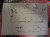
It was easier to sketch it than photograph. That would have meant turning it off.....")
So bear in mind that the layout used here is most likely not ideal. I used it because it suited a case I already had (holes drilled etc). So I'm sure having the 4 valves nearer one another or laid out in a different way would be better.
So, the basic premise is that 1 long bar runs along the lenght of the 4 valves. Low current grounds (inputs and input valve cathodes) are connected right at one end. Next up along are all the RIAA grounds (close to the input grounds) and then right at the far end of the bar I have connected the PSU ground, output grounds, heater ground, connection to chassis and the output cathode grounds. The shields on the 2 x 6N2 are along the bar.
As I said, I'm sure there are better ways, but I now have very low hum.
http://www.diyaudio.com/forums/attachment.php?attachmentid=222297&stc=1&d=1304973716
Fran
It was easier to sketch it than photograph. That would have meant turning it off.....
So bear in mind that the layout used here is most likely not ideal. I used it because it suited a case I already had (holes drilled etc). So I'm sure having the 4 valves nearer one another or laid out in a different way would be better.
So, the basic premise is that 1 long bar runs along the lenght of the 4 valves. Low current grounds (inputs and input valve cathodes) are connected right at one end. Next up along are all the RIAA grounds (close to the input grounds) and then right at the far end of the bar I have connected the PSU ground, output grounds, heater ground, connection to chassis and the output cathode grounds. The shields on the 2 x 6N2 are along the bar.
As I said, I'm sure there are better ways, but I now have very low hum.
http://www.diyaudio.com/forums/attachment.php?attachmentid=222297&stc=1&d=1304973716
Fran
Attachments
I have seen them on their Mix comeback tour in Liverpool 20yrs ago. TEE was hypnotic with the wheels revolution video in the classic theatre decor.
After making a 60dB gain valve circuit quiet, what you learn is a boon for working on HV & vacuum. What is your ICCS? Maybe you can shave off some? High heater regs sink temp too?
After making a 60dB gain valve circuit quiet, what you learn is a boon for working on HV & vacuum. What is your ICCS? Maybe you can shave off some? High heater regs sink temp too?
sounds even better after a glass! R1 is 47r...... so maybe I could shave a bit off. Heater regs have puny sinks anyway so I'm probably going to change those anyway. I have some bigger ones I could use. It's just that when it's boxed up there will probably be 10 degree more heat easily.
Fran
See your voltage drop across the 47R, then divide by 47R. That is the CCS current. Two itch channels are draining ~10mA. See to have 30-35mA CCS total. 20-25mA are OK for the reg to consume internally for proper Zo. Each 10mA extra spare is 3W dissipation @ 300V on the IRF840...
Just to clear something up, from Salas' advise on bar grounding, I thought that the bar should only see chassis ground at the input end and power ground at the output end.
However, Fran's sketch shows chassis ground at the PSU grounded end. Naturally, Fran, if it sounds good, it is good. I just thought I'd make sure I hadn't missed something.

Regards,
Tani.
On a bar we ground at the input side to chassis only, and we go from lighter to heavier currents in a row on it ending at PSU. Something must be mixing there most likely.
However, Fran's sketch shows chassis ground at the PSU grounded end. Naturally, Fran, if it sounds good, it is good. I just thought I'd make sure I hadn't missed something.
Regards,
Tani.
Just to clear something up, from Salas' advise on bar grounding, I thought that the bar should only see chassis ground at the input end and power ground at the output end.
However, Fran's sketch shows chassis ground at the PSU grounded end. Naturally, Fran, if it sounds good, it is good. I just thought I'd make sure I hadn't missed something.
Regards,
Tani.
From the linked article: ''You only want your buss to connect to chassis ground at one point, either at the power supply first filter cap or at the other end of the buss at the input jack. If you connect the buss to ground at the power supply, you will need to use an isolated input jack (run the shield connection over to the ground point of the cathode components of the first stage). Then you will need to add a 0.01uF capacitor (ceramic disk caps are good for this) from the shield terminal of the input jack directly to the chassis with the shortest possible wires. This will keep radio frequencies from getting into the amp.''
So it can work both ways depending on input sensitivity and PSU nodes distribution. I usually go to chassis input side. I use the small capacitors (MKT for me) from RCA rings to nearest chassis spot in phonos if I ground at the PSU end. I don't necessarily take the plastic spacers out if I ground input side, I chassis ground the bar on a screw and nut near the inputs and link them RCA rings there too. By ''only'' I mean chassis link at one point.
Use shielded coax for inputs and outputs as well. Pushes hum lowest.
On that note, is it best practice to use 2-wire plus shield, with the wires carrying signal and ground, and the shield grounded only at the input end. Or should I use single wire shielded cable, similar to standard RCA interconnects, with the shield carrying the signal ground? Or...?
In an op-amp phono pre, I once used 2-wire plus shield to carry left and right signals, with the shield carrying a common ground. I knew full well that it wasn't likely to be the best configuration, but I thought I'd try. I suspected that cross talk would suffer, but it seems OK when listening... I get an indication of cross talk by disconnecting left input and right speaker output and play music... whatever makes it to the speaker has crossed over from the other channel, correct? Of course it doesn't tell you where the cross talk is coming from...
Tani.
Things just got quieter round here.....
I went back and rewired the inputs and outputs and input 6n2 cathodes to ground with shielded cabke. Like in the articke, I then took a 0.01uf cap from each input jack plus the shields to the chassis right at the input jacks. Interestingly, I first tried running a short piece of wire from the 3 caps to the ground point, this was about 50mm long. Result was buzz, at low level but still there. Cutting the wire short and tying to the chassis closer made all the difference.
So now that done its dead quiet. Listening now for a little while and then try the k42y coupling caps.
Fran
So now that done its dead quiet.
Fran
Sounds like a proper Itch.
- Home
- Source & Line
- Analogue Source
- Valve Itch phono