The simplest and cheapest approach is to ground the negative outputs of the main PCB (with the 10 uF DC blocker capacitors still in place) and to use single-ended filters. I tried that on the complete valve DAC and got an increase of about 3 dB of the noise floor, but otherwise it worked fine.
The simplest and cheapest approach is to ground the negative outputs of the main PCB (with the 10 uF DC blocker capacitors still in place) and to use single-ended filters. I tried that on the complete valve DAC and got an increase of about 3 dB of the noise floor, but otherwise it worked fine.
Thanks Marcel and, yes, I'll probably try that in the first instance or, maybe, even one of these (just to prove the DAC works - I've got a spare one here somewhere);
DRV603 board - I2S over USB Audio
So Marcel, I think that's the incoming data and flags taken care of;
https://www.diyaudio.com/forums/digital-line-level/254935-signalyst-dsc1-145.html#post5854542
It does beg one extra request for the Valve DAC PCB though, as Pavel's reclocker doesn't have ufl outputs for the DSD data, could you include the option for an Amanero pattern connector on the valve DAC PCB so the boards could plug together, keeping data paths nice and short? Sorry to ask you and I know we thought ufl connectors would be good (and still warranted) but an Amanero connector would give simple options for input source components - Pavel's reclocker, Amanero USB board plus others such as (I believe) DIYINHK's USB isolator/reclocker boards.
On the ouput side, I found the little JLSounds board with the reconstruction filter and balanced to SE conversion. I don't know what the filter frequency or type is (have asked) but my reasoning to use it in the first instance is to just prove the DSD-only Valve DAC works functionally without having to invest in building an output filter/buffer board - that will follow if all is well with plenty of opportunity to optimise it through experimentation.
Cheers
Ray
Please see the attachments for my raw DSD PCB design. The files are meant for a four-layer board process with prepreg layers of about 360 um thick (like Eurocircuits proto). I'll write a more extensive explanation after sleeping.
Attachments
Please see the attachments for my raw DSD PCB design. The files are meant for a four-layer board process with prepreg layers of about 360 um thick (like Eurocircuits proto). I'll write a more extensive explanation after sleeping.
That looks good Marcel. I'll have a closer look later but I think you've done an ace job.
 Thanks for being responsive to my requests.
I quickly loaded the gerbers into one of the Chinese PCB fabrication websites (without looking closely at the layer thicknesses) and it looks like less that 100USD for five boards and an SMD stencil, including shipping.
Attached are a more elaborate explanation, a bill of materials (zipped because the forum doesn't allow .csv files) and a gerbers.zip archive that includes a .d356 netlist; I don't know what those are used for, but some PCB manufacturers like to receive them.
Attachments
Thanks Marcel.
I've been costing up PCBs from JLCPCB, they're significantly cheaper than the Eurocircuits prototype service even if I specify a 2mm thick board to mitigate the PCB flexing when inserting/extracting valves from their sockets.
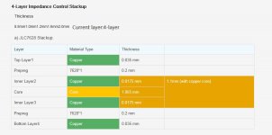
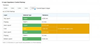
What i have noticed though is that JLC's copper layers seem to be reversed compared with eurocircuits, here's the info on the JLC layers;
I've been costing up PCBs from JLCPCB, they're significantly cheaper than the Eurocircuits prototype service even if I specify a 2mm thick board to mitigate the PCB flexing when inserting/extracting valves from their sockets.
What i have noticed though is that JLC's copper layers seem to be reversed compared with eurocircuits, here's the info on the JLC layers;
Attachments
Last edited:
With Eurocircuits the inner copper is thicker than the outer, with JLC the inner copper is thinner than the outer.
I noticed the pre-preg difference - the core layer of the JLC board is 1mm thick compared with 0.7mm for eurocircuits - outside of the core, the JLC uses 1 layer of PPR7628 pre-preg compared with two layers for eurocircuits, but with a 2mm thick board from JLC I believe it will also have 2 layers of the pre-preg.
I noticed the pre-preg difference - the core layer of the JLC board is 1mm thick compared with 0.7mm for eurocircuits - outside of the core, the JLC uses 1 layer of PPR7628 pre-preg compared with two layers for eurocircuits, but with a 2mm thick board from JLC I believe it will also have 2 layers of the pre-preg.
That would be nice, because then I don't have to change the microstrip lines or to check whether 200 um prepreg thickness is enough for 400 V.
I'll contact JLC to try and confirm that the 2mm PCB has two layers of the pre-preg.
Can I assume that the copper thicknesses being reversed doesn't concern you?
I've been studying the PCB with a gerber viewer and it looks excellent - thank you so much for putting in the effort to make this DSD version.
The only question I have is about the position of the input connectors and associated components relative to the DAC cores, which results in some quite long PCB tracks for the data/clock signals?
Thanks
Ray
I found the answer and I was mistaken, the 2mm thick PCB just has a thicker core layer and only a single layer of the pre-preg between the inner and outer coppers.I'll contact JLC to try and confirm that the 2mm PCB has two layers of the pre-preg.
Attachments
And I just found out the PCB is too big for my friends reflow oven!
If I do need to go to Eurocircuits for the PCB I wonder how much it will cost to have them assemble the smd components too?
Marcel, I notice that your BOM lists most of the smd parts as for hand soldering - is there anything I would need to do in KiCAD to facilitate eurocircuits doing the assembly of these parts as I assume they'll have pick and place?
I'll contact JLC to try and confirm that the 2mm PCB has two layers of the pre-preg.
In principle a single layer of prepreg should easily be able to handle 300 to 400 V. That does not take into account possible voids, though. With a double prepreg layer problems due to voids are unlikely. See multi layer - High Voltage Multilayer PCB - Electrical Engineering Stack Exchange
If you want to go for a single prepreg layer of 200 um, I'll make a version with a few transmission lines made narrower. What is the narrowest line width that JLC allows?
Can I assume that the copper thicknesses being reversed doesn't concern you?
Not much, no. Maybe I have to check the heater wiring width just to be sure, but the heater current is far less than it used to be.
I've been studying the PCB with a gerber viewer and it looks excellent - thank you so much for putting in the effort to make this DSD version.
The only question I have is about the position of the input connectors and associated components relative to the DAC cores, which results in some quite long PCB tracks for the data/clock signals?
Thanks
Ray
This is a consequence of trying to stay as close as possible to the original. In the original version, the data came from the FPGA board that I deliberately placed at some distance from the DAC cores. I now put the data and clock buffers in the hole left by the removed FPGA board, S/PDIF interface and ASRC.
And I just found out the PCB is too big for my friends reflow oven!
If I do need to go to Eurocircuits for the PCB I wonder how much it will cost to have them assemble the smd components too?
Marcel, I notice that your BOM lists most of the smd parts as for hand soldering - is there anything I would need to do in KiCAD to facilitate eurocircuits doing the assembly of these parts as I assume they'll have pick and place?
I didn't realize you wanted to use a reflow oven. I don't know if Eurocircuits has an assembly service. I used the KiCAD handsoldering footprints where available to make handsoldering easier. The difference with the regular footprint is that the pads are slightly longer. No idea what harm that does to automated assembly processes.
I didn't realize you wanted to use a reflow oven. I don't know if Eurocircuits has an assembly service. I used the KiCAD handsoldering footprints where available to make handsoldering easier. The difference with the regular footprint is that the pads are slightly longer. No idea what harm that does to automated assembly processes.
Hi Marcel.
Using my friends reflow oven would have been a good approach to soldering the smd parts, probably much more reliable than my hand soldering, however, I have a hot air station and my friend, who has much more experience of smd work (and better hands/eyes) than me has also offered to help so I think things will work out.
Eurocircuits does have an assembly service and I had a bit more of a look after I posted. To use it would mean quite a bit more preparation work and it's not cheap so I think I'll stick with manual assembly. For an experienced PCB designer it would probably be quick an easy but I can do without the steep learning curve.
Ray
I think you've already made a very significant contribution Marcel and I think I'll put my hand in my pocket and buy a board from Eurocircuits rather than have you spend any more time reworking the board for me.
I had deduced that was the case and you seem to have had no problems with the length of tracks on your original boards, with the FPGA, so whilst it would be nice to move the input section I don't think it is critical so we can go with the board layout you've produced.
Ray
This is a consequence of trying to stay as close as possible to the original. In the original version, the data came from the FPGA board that I deliberately placed at some distance from the DAC cores. I now put the data and clock buffers in the hole left by the removed FPGA board, S/PDIF interface and ASRC.
I had deduced that was the case and you seem to have had no problems with the length of tracks on your original boards, with the FPGA, so whilst it would be nice to move the input section I don't think it is critical so we can go with the board layout you've produced.
Ray
Hi Marcel, would you be interested if I looked into a group buy for this board? It would be nice to update things and not just leave the other board group buy without closure.
Assuming you're talking about the DSD-only board that Marcel has been helping me with, with Marcel's agreement I would like to see if there is any interest in this board from other DSD enthusiasts. I'm aware of the previous group buy as a possible source of interest and I think also the Signalyst DSC decoder thread. I'm wondering if there needs to be a working prototype before getting too carried away though.
Did you have any joy with finding a PCB fabricator that can deliver to similar specs to the Eurocircuits layering at a good price with the previous group buy.
Also, I haven't raised this with Marcel (well, until now) but I've been wondering if the DSD-only version might be suitable for PCM with a different FPGA module on the front end that takes care of clocking etc. with silicon technology (so not quite meeting the requirements in section 1 of Marcel's original Valve DAC article but still exploiting valves in the DAC core).
Ray
- Home
- Source & Line
- Digital Line Level
- Valve DAC from Linear Audio volume 13