I have this one that I made in Curve Captor.
Code:* ============================================================== * 6N27P LTSpice model * Vp max=30V * Rydel model (5 parameters): mean fit error 0.0929598mA * Traced by Wayne Clay on 02/20/2019 using Engauge Digitizer 10.4 * and Curve Captor v0.9.1 from Soviet data sheet. * ============================================================== .subckt 6N27P P G K Bp P K I= + ((0.06761422227m)+(0.02514297819m)*V(G,K))*uramp((10.49851918)*V(G,K)+ + V(P,K)+(3.457647953))**1.5 * V(P,K)/(V(P,K)+(0.1934578768)) Cgp G P 2.0p ; 0.7p added (1.3p) Cgk G K 3.7p ; 0.7p added (3.0p) Cpk P K 0.4p ; 0.2p added (0.2p) Cps P 0 1.6p ; Plate to shield (shield connected to ground) Rpk P K 1.0G ; to avoid floating nodes d3 G K dx1 .model dx1 d(is=1n rs=2k cjo=1pf N=1.5 tt=1n) .ends 6N27P
I don't like that model.
I found this one on the net:
Code:
.subckt ecc86_krn  1 2 3 ; placca griglia catodo
********************************************
;modello valido nell’intorno vp=0..10volt
********************************************
+ params: mu=14 ex=1.71 kg1=295 kp=220 kvb=100 rgi=2k
+ ccg=3p cgp=1.3p ccp=1.8p
+ a2=0.0083 a1=-0.022 a0=1.1033
e1 7 0 value=
+{v(1,3)/kp*ln(1+exp(kp*(1/mu+v(2,3)/sqrt(kvb+v(1,3)*v(1,3)))))}
re1 7 0 1g
e2 8 0 value=
+{a2*v(1,3)*v(1,3)+a1*v(1,3)+a0}
re2 8 0 1g
g1 1 3 value= {(pwr(v(7),v(8))+pwrs(v(7),v(8)))/kg1}
rcp 1 3 1g
c1 2 3 {ccg}
c2 1 2 {cgp}
c3 1 3 {ccp}
r1 2 5 {rgi}
d3 5 3 dx
.model dx d(is=1n rs=1 cjo=10pf tt=1n)
.endsThat model is way off from the data sheet. Looks a little "out there".I don't like that model.
I found this one on the net:
What do you think?Code:.subckt ecc86_krn 1 2 3 ; placca griglia catodo ******************************************** ;modello valido nell’intorno vp=0..10volt ******************************************** + params: mu=14 ex=1.71 kg1=295 kp=220 kvb=100 rgi=2k + ccg=3p cgp=1.3p ccp=1.8p + a2=0.0083 a1=-0.022 a0=1.1033 e1 7 0 value= +{v(1,3)/kp*ln(1+exp(kp*(1/mu+v(2,3)/sqrt(kvb+v(1,3)*v(1,3)))))} re1 7 0 1g e2 8 0 value= +{a2*v(1,3)*v(1,3)+a1*v(1,3)+a0} re2 8 0 1g g1 1 3 value= {(pwr(v(7),v(8))+pwrs(v(7),v(8)))/kg1} rcp 1 3 1g c1 2 3 {ccg} c2 1 2 {cgp} c3 1 3 {ccp} r1 2 5 {rgi} d3 5 3 dx .model dx d(is=1n rs=1 cjo=10pf tt=1n) .ends
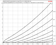
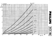
Here's an ECC86 model I just made from the Philips data sheet:
Code:
* ==============================================================
* ECC86 LTSpice model
* Rydel model (5 parameters) mean fit error 0.0841046mA
* Traced by Wayne Clay on 03/31/2021 using Curve Captor v0.9.1
* and Engauge Digitizer from Philips datasheet.
* ==============================================================
.subckt ECC86  P G K
    Bp  P K  I=((0.06448068329m)+(0.02426328916m)*V(G,K))*uramp((11.97388325)*V(G,K)+V(P,K)+(5.140204023))**1.5 * V(P,K)/(V(P,K)+(0.5451602865))
    Cgp G P 2.0p ; 0.7p added (1.3p)
    Cgk G K 3.7p ; 0.7p added (3.0p)
    Cpk P K 2.0p ; 0.2p added (1.8p)
    Rpk P K 1.0G ; to avoid floating nodes
    d3  G K dx1
.model dx1 d(is=1n rs=2k cjo=1pf N=1.5 tt=1n)
.ends ECC86")
Attachments
6EW6 spice model
I don't have a 6BN11 model, but I do have a 6EW6 model. They both appear to be very similar, if not the same. 2 6EW6's in one bottle.This is a long shot - anyone ever come across a 6EW6 or 6BN11 model?
Code:
**** 6EW6 ******************************************
* Created on 07/24/2018 13:40 using paint_kit.jar 2.6
* [URL="http://www.dmitrynizh.com/tubeparams_image.htm"]www.dmitrynizh.com/tubeparams_image.htm[/URL]
* Plate Curves image file: 6EW6.gif
* Data source link:
*----------------------------------------------------------------------------------
.SUBCKT 6EW6 1 4 2 3 ; P G2 G K
+ PARAMS: CCG=10P  CGP=0.04P CCP=2.4P RGI=2000
+ MU=65.5 KG1=320 KP=355.4 KVB=4.79 EX=1.4 KG2=750 ; KG2=359.5
* Vp_MAX=500 Ip_MAX=28 Vg_step=0.5 Vg_start=0 Vg_count=5
* Rp=1600 Vg_ac=23.5 P_max=3.1 Vg_qui=-23.4 Vp_qui=240 UL=0.43 EG2=125
* X_MIN=44 Y_MIN=47 X_SIZE=705 Y_SIZE=494 FSZ_X=1604 FSZ_Y=869 XYGrid=false
* showLoadLine=n showIp=y isDHT=n isPP=n isAsymPP=n isUL=n showDissipLimit=y
* showIg1=n gridLevel2=n isInputSnapped=n
* XYProjections=n harmonicPlot=y harmonics=y
*----------------------------------------------------------------------------------
RE1  7 0  1MEG    ; DUMMY SO NODE 7 HAS 2 CONNECTIONS
E1   7 0  VALUE=  ; E1 BREAKS UP LONG EQUATION FOR G1.
+{V(4,3)/KP*LOG(1+EXP((1/MU+V(2,3)/V(4,3))*KP))}
G1   1 3  VALUE={(PWR(V(7),EX)+PWRS(V(7),EX))/KG1*ATAN(V(1,3)/KVB)}
*G2   4 3  VALUE={(EXP(EX*(LOG((V(4,3)/MU)+V(2,3)))))/KG2}
G2 8 3 VALUE={(PWR(V(7),EX)+PWRS(V(7),EX))/KG2*(2.5708-ATAN(V(1,3)/KVB))}
E2 8 4 VALUE={0}
RCP  1 3  1G      ; FOR CONVERGENCE
C1   2 3  {CCG}    ; CATHODE-GRID 1
C2   1 2  {CGP}  ; GRID 1-PLATE
C3   1 3  {CCP}   ; CATHODE-PLATE
R1   2 5  {RGI}   ; FOR GRID CURRENT
D3   5 3  DX      ; FOR GRID CURRENT
.MODEL DX D(IS=1N RS=1 CJO=10PF TT=1N)
.ENDS
*$
Attachments
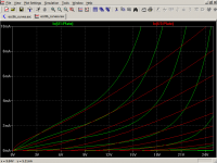
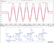
THanks cogsncogsGreen curves = ecc86_krn model
Red curves = ECC86 Philips Rydel 5 model.
(...)
Here's an ECC86 model I just made from the Philips data sheet (...)
Hi all
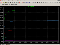
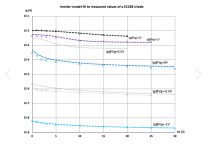
Please note that the ECC86's gridcurrent-free headroom is super small. You have to stay below -0.75V gridvoltage. At -0.5V or more positive, you will have a no longer ignorable gridcurrent which causes significant voltage drop across a 1Meg grid resistor. See my measurements attached.
Note that most ECC86 spice models have a poor grid current quality which may let you trust in simulation results that are not possible in reality...
all the best, Adrian
PS: This tube was intended for high frequency stages in 12V powered car radios - such circuits had no need for a large headroom
Attachments
Thanks.Hi all
Please note that the ECC86's gridcurrent-free headroom is super small. You have to stay below -0.75V gridvoltage. At -0.5V or more positive, you will have a no longer ignorable gridcurrent which causes significant voltage drop across a 1Meg grid resistor. See my measurements attached.
Note that most ECC86 spice models have a poor grid current quality which may let you trust in simulation results that are not possible in reality...
all the best, Adrian
PS: This tube was intended for high frequency stages in 12V powered car radios - such circuits had no need for a large headroom
@Adrian Immler
Can you give an example of a ECC86 circuit that is acceptable?
And one that will not work?
I have 5 ECC86 tubes.
I want to use 30 Volt supply.
Last edited:
Hi lineup
With the small signal amplitude you use and a bias of -1V, the results are ok.
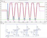
Here is the promised ECC86 model comparison. I used a 1Vrms signal. At this level, the models differ much. Please note:
1) The Wayne Clay (cogsncogs) model tells you a more or less undistorted output signal. The grid just starts to rectify a bit. But reality is much more worse.
2) There will be strong bias shifting because of the grid acting as a rectifier
3) The krn model shows this effect also, but not as strong as a real tube will do.
4) The krn model shows too hard clipping. A real tube clips much softer.
5) Wayne Clay and krn model deliver a too big amplitude of the output signal
regards, Adrian
With the small signal amplitude you use and a bias of -1V, the results are ok.
Here is the promised ECC86 model comparison. I used a 1Vrms signal. At this level, the models differ much. Please note:
1) The Wayne Clay (cogsncogs) model tells you a more or less undistorted output signal. The grid just starts to rectify a bit. But reality is much more worse.
2) There will be strong bias shifting because of the grid acting as a rectifier
3) The krn model shows this effect also, but not as strong as a real tube will do.
4) The krn model shows too hard clipping. A real tube clips much softer.
5) Wayne Clay and krn model deliver a too big amplitude of the output signal
regards, Adrian
Attachments
... at 0.4Vrms Input signal, the rectifying effect just starts. Below that value, all 3 models delivers similar anode bias voltages. The krn model has a too big gain.
How ever, for your small signal levels, cogsncogs model is ok.
Happy Easter!
cheers, Adrian
How ever, for your small signal levels, cogsncogs model is ok.
Happy Easter!
cheers, Adrian
Attachments
Hi Adrian,
The reason for the diode in my model(s) is to help with convergence if the tube/valve is used as a cathode follower that is direct coupled to the previous stage. I've found that in Micro Cap 6 in some instances that if the diode is not present, Micro Cap 6 would fail to converge. I now have MC12, so I don't know if that would be a problem in MC12. In my models grid current is not modeled, though the diode does give some semblance of G1 current, poor as it is.
I don't mess with instrument amplifiers, just "hi-fi". I know from experience where to stay away from as to Vgk. My models are from the published curves as opposed from a real valve you may be holding in your hand. As a result I do not put much stock in distortion results (0.001%?) in a simulation, just as a guide. Your 12AX7/ECC83 model for Ig1 is the bees knees (To be exceptionally great, excellent, or high-quality.) for a "zero bias" stage. I have much respect for your work. 
The reason for the diode in my model(s) is to help with convergence if the tube/valve is used as a cathode follower that is direct coupled to the previous stage. I've found that in Micro Cap 6 in some instances that if the diode is not present, Micro Cap 6 would fail to converge. I now have MC12, so I don't know if that would be a problem in MC12. In my models grid current is not modeled, though the diode does give some semblance of G1 current, poor as it is.
I don't mess with instrument amplifiers, just "hi-fi"
. I know from experience where to stay away from as to Vgk. My models are from the published curves as opposed from a real valve you may be holding in your hand. As a result I do not put much stock in distortion results (0.001%?) in a simulation, just as a guide. Your 12AX7/ECC83 model for Ig1 is the bees knees (To be exceptionally great, excellent, or high-quality.) for a "zero bias" stage. I have much respect for your work. Hi Adrian,
I just wanted to thank you for the work you've been doing, and especially for the 6N6P model (for one of my favorite triodes). But really, all of them are valuable additions, and it's very generous of you to offer them up for all of us.
Much gratitude!
--
PS - It's remarkable how well the ECC86_i2 imitates a real life grid current waveform!
Hi Wayne, Hi rongon,
thank you both for the positive feedback. That motivates me to continue with "tube spicing". But I don't like to be adored. Just want to point to the One who is worth for that - as he "carried the cross and all our shame", to use Bono's words from his famous "still haven't found..." song.
Happy Easter!
Adrian
PS: When I remember right, I still should have somewhere an ECC86 sample... I hope to find it, for a sim-versus-real-tube comparison.
- Home
- Amplifiers
- Tubes / Valves
- Vacuum Tube SPICE Models