Just pop in the new parameters:
.subckt 12HL7 1 2 3
+Params: MU=25.4 KP=431 KVB=1 EX=1.59 KG1=213
E1 7 0 Value = {(V(1,3)/KP)*LN((1+ EXP((KP/MU) + ((KP*(V(2,3)+.5))/(SQRT(KVB+V(1,3)*V(1,3)))))))}
RE1 7 0 1e12
G1 1 3 VALUE = {(((V(7))^EX)/KG1)*(1+SGN(V(7)))}
RCP 1 3 2.3e12
C1 2 3 2.3e-12
C2 1 2 2.1e-12
C3 1 3 0.7e-12
R1 2 5 2000
D3 5 3 dx
.model dx d(is=1e-09 rs=1 cjo=10e-12)
.ends
Oh, I think a light bulb just went on. Thanks for this.
Incidentally, do I need to change the "^" to "**" for use in LTspice? (I think I do, but I'd have to wait until this evening to experiment with it...)
Also, I assume 1 = A (anode), 2 = G (grid), 3 = K (cathode) ... correct?
--
Incidentally, do I need to change the "^" to "**" for use in LTspice? (I think I do, but I'd have to wait until this evening to experiment with it...)
Also, I assume 1 = A (anode), 2 = G (grid), 3 = K (cathode) ... correct?
--
I've got kevinkr's for 4P1L-triode:
I've also got this Ayumi model for tetrode:Code:* n* library format: LTSpice * Traced by Kevin Kennedy 2014-04-18 in uTgui * Unselected sample .SUBCKT 4P1L-TRI 1 2 3 ; P G C (Triode) X1 1 2 3 TRIODE MU=10.25 EX=1.48 KG1=1177.7 KP=631.61 KVB=376.5 VCT=0.00 RGI=2000 CCG=0p CPG1=0p CCP=0p ; .ENDS 4P1L-TRI
Strap g2 to the anode and it's a triode, right? It should work.Code:* * Generic pentode model: 4P1L_AN * Copyright 2003--2008 by Ayumi Nakabayashi, All rights reserved. * Version 3.10, Generated on Wed Jan 08 17:33:48 2014 * Plate * | Screen Grid * | | Control Grid * | | | Cathode * | | | | .SUBCKT 4P1L_AN A G2 G1 K BGG GG 0 V=V(G1,K)+1 BM1 M1 0 V=(0.020703576*(URAMP(V(G2,K))+1e-10))**-0.32815356 BM2 M2 0 V=(0.8205*(URAMP(V(GG)+URAMP(V(G2,K))/8.67)))**1.8281536 BP P 0 V=0.0016959897*(URAMP(V(GG)+URAMP(V(G2,K))/10.566728))**1.5 BIK IK 0 V=U(V(GG))*V(P)+(1-U(V(GG)))*0.00103*V(M1)*V(M2) BIG IG 0 V=0.00084799486*URAMP(V(G1,K))**1.5*(URAMP(V(G1,K))/(URAMP(V(A,K))+URAMP(V(G1,K)))*1.2+0.4) BIK2 IK2 0 V=V(IK,IG)*(1-0.4*(EXP(-URAMP(V(A,K))/URAMP(V(G2,K))*15)-EXP(-15))) BIG2T IG2T 0 V=V(IK2)*(0.857*(1-URAMP(V(A,K))/(URAMP(V(A,K))+10))**1.5+0.143) BIK3 IK3 0 V=V(IK2)*(URAMP(V(A,K))+908)/(URAMP(V(G2,K))+908) BIK4 IK4 0 V=V(IK3)-URAMP(V(IK3)-(0.0010943584*(URAMP(V(A,K))+URAMP(URAMP(V(G2,K))-URAMP(V(A,K))))**1.5)) BIP IP 0 V=URAMP(V(IK4,IG2T)-URAMP(V(IK4,IG2T)-(0.0010943584*URAMP(V(A,K))**1.5))) BIAK A K I=V(IP)+1e-10*V(A,K) BIG2 G2 K I=URAMP(V(IK4,IP)) BIGK G1 K I=V(IG) * CAPS CGA G1 A 0.1p CGK G1 K 5.6p C12 G1 G2 3.7p CAK A K 8.5p .ENDS
I also have Ale's models, but I can never get those to work in LTspice.
Thank you kind sir!
I must have missed Kevin's post on first glance, I will see how that triode model and "strapping" the pentode model compare.
I wonder if Ale's model is for PSpice or some other sim software? I think if I rearrange his model in a particular fashion I may be able to get it to work, I have done it for other models before. BUT since I don't really plan on a build using this particular tube I doubt I will go through the trouble now that I have these. Ale's models do look very close to the actual triode curves though

yesAlso, I assume 1 = A (anode), 2 = G (grid), 3 = K (cathode) ... correct?
--
you have to make sure that all the "parens" are properly nested.
Incidentally, with no apologies whatsoever to Koren and the phenomenological models, but rather a compliment, my high school does a wonderful job with physics class --- they make the young folk do the experiments, tabulate the data, and then figure what properties make which equations work starting with the "frictionless puck"
Thank you kind sir!
I must have missed Kevin's post on first glance, I will see how that triode model and "strapping" the pentode model compare.
I wonder if Ale's model is for PSpice or some other sim software? I think if I rearrange his model in a particular fashion I may be able to get it to work, I have done it for other models before. BUT since I don't really plan on a build using this particular tube I doubt I will go through the trouble now that I have these. Ale's models do look very close to the actual triode curves though
It does indeed and it was made for LTSpice
")
Just make sure you have a 4-element DHT symbol as the model is for 4 pin triodes (2 for filament).
I updated the model with A2 grid curves:http://www.bartola.co.uk/valves/2013/09/29/4p1l-model-improved/

**** 4P1L TRIODE version 4 ** Composite DHT with Advanced Grid Current **************
* Created on 09/29/2013 08:35 using paint_kit.jar Version 2.4 Beta. May 2013
* Bartola Valves | All about electronic valves and hi-fi
* Created by Ale Moglia valves@bartola.co.uk using uTracer
* Plate Curves image file: 4P1L TRIODE 4
* Plate Data source link: Bartola Valves | All about electronic valves and hi-fi
*----------------------------------------------------------------------------------
.SUBCKT DHT_4P1L 4_A2 1 2 3 4 ; P G K1 K2
+ PARAMS: CCG=6P CGP=8P CCP=4P RFIL=13.5
+ MU=9.5 KG1=855 KP=150 KVB=745.3 VCT=0.407 EX=1.4
+ VGOFF=-3.94 IGA=0.01 IGB=0.432 IGC=11.8 IGEX=1.92
* Vp_MAX=350 Ip_MAX=140 Vg_step=5 Vg_start=10 Vg_count=9
* Rp=4000 Vg_ac=55 P_max=9 Vg_qui=-48
* X_MIN=77 Y_MIN=89 X_SIZE=492 Y_SIZE=526 FSZ_X=1157 FSZ_Y=724 XYGrid=false
*----------------------------------------------------------------------------------
RFIL_LEFT 3 31 {RFIL/4}
RFIL_RIGHT 4 41 {RFIL/4}
RFIL_MIDDLE1 31 34 {RFIL/4}
RFIL_MIDDLE2 34 41 {RFIL/4}
E11 32 0 VALUE={V(1,31)/KP*LOG(1+EXP(KP*(1/MU+V(2,31)/SQRT(KVB+V(1,31)*V(1,31)))))}
E12 42 0 VALUE={V(1,41)/KP*LOG(1+EXP(KP*(1/MU+V(2,41)/SQRT(KVB+V(1,41)*V(1,41)))))}
RE11 34 0 1G
G11 1 31 VALUE={(PWR(V(32),EX)+PWRS(V(32),EX))/(2*KG1)}
G12 1 41 VALUE={(PWR(V(42),EX)+PWRS(V(42),EX))/(2*KG1)}
RCP1 1 34 1G
C1 2 34 {CCG} ; CATHODE-GRID
C2 2 1 {CGP} ; GRID=PLATE
C3 1 34 {CCP} ; CATHODE-PLATE
RE2 2 0 1G
EGC1 81 0 VALUE={V(2,31)-VGOFF} ; POSITIVE GRID THRESHOLD
GG1 2 31 VALUE={0.5*(IGA+IGB/(IGC+V(1,31)))*(MU/KG1)*(PWR(V(81),IGEX)+PWRS(V(81),IGEX))}
EGC2 82 0 VALUE={V(2,41)-VGOFF} ; POSITIVE GRID THRESHOLD
GG2 2 41 VALUE={0.5*(IGA+IGB/(IGC+V(1,41)))*(MU/KG1)*(PWR(V(82),IGEX)+PWRS(V(82),IGEX))}
.ENDS
*$
Hope this helps
Ale
mogliaa said:Just make sure you have a 4-element DHT symbol as the model is for 4 pin triodes (2 for filament).
Ale, can you post the 4-element DHT symbol you use with LTspice? Is it a .asy file? Thanks.
--
added later:
I'd like to make a .asy model for a 4-element DHT, so I can save your found parameters for various DHTs in text files in my LTspice /sub folder, and call them up within a schematic from the devices pick list. (I hope that makes sense.) Is this as simple as taking a pre-existing .asy file for a tetrode (for example) and renaming pin elements 1, 2, 3, and 4 from P, G2, G1, and K to P, G, K1, and K2?
thanks for any help with this.
Last edited:
Ale, can you post the 4-element DHT symbol you use with LTspice? Is it a .asy file? Thanks.
I use triodedht.asy.
Version 4
SymbolType CELL
LINE Normal -48 0 -28 0
LINE Normal -20 0 -12 0
LINE Normal -4 0 4 0
LINE Normal 12 0 20 0
LINE Normal 28 0 36 0
LINE Normal 0 -48 0 -16
LINE Normal -20 -16 20 -16
LINE Normal -20 -12 20 -12
LINE Normal -20 -16 -20 -12
LINE Normal 20 -16 20 -12
LINE Normal 16 32 16 65
LINE Normal -16 33 -16 65
LINE Normal 1 24 16 32
LINE Normal -16 33 1 24
CIRCLE Normal -48 -48 48 48
WINDOW 0 8 -64 Left 0
WINDOW 3 62 -29 Left 0
SYMATTR Value TriodeDHT
SYMATTR Prefix X
SYMATTR Description This symbol is for use with a subcircuit macromodel that you supply.
PIN 0 -48 NONE 0
PINATTR PinName P
PINATTR SpiceOrder 1
PIN -48 0 NONE 0
PINATTR PinName G
PINATTR SpiceOrder 2
PIN -16 64 NONE 0
PINATTR PinName K1
PINATTR SpiceOrder 3
PIN 16 64 NONE 8
PINATTR PinName K2
PINATTR SpiceOrder 4
Looking for Spice model of 6F12P (6Ф12П) both Triode and Pentode;
found that pentode model here, but does not emulate IG2 very well, too low;
and no triode model at all;
.SUBCKT 6F12PP 1 2 3 4 ; P G1 C G2 (Pentode) 28-Feb-2008
+ PARAMS: MU= 71.45 EX= 1.350 KG1= 260.8 KP=7396.95 KC= 4000
+ KVB= 17.9 VCT= 0.00 RGI= 4500k
+ CCG=6.6P CPG1=0.02P CCP=1.9P
RE1 7 0 1G
RE2 8 4 1G
E1 7 0 VALUE={V(2,4)/KP*LOG(1+EXP((1/MU+V(3,4)/V(2,4))*KP))}
G1 1 4 VALUE={(PWR(V(7),EX)+PWRS(V(7),EX))/KG1*1.57*TANH(2*V(1,4)/(KVB*3.14159))}
G2 8 4 VALUE={(PWR(V(7),EX)+PWRS(V(7),EX))/KC*(2.57-1.57*TANH(2*V(1,4)/(KVB*3.14159)))}
E2 8 2 VALUE={0}
RCP 1 4 1G ; FOR CONVERGENCE
C1 3 4 {CCG} ; CATHODE-GRID 1
C2 1 3 {CPG1} ; GRID 1-PLATE
C3 1 4 {CCP} ; CATHODE-PLATE
R1 3 5 {RGI} ; FOR GRID CURRENT
D3 5 4 DX ; FOR GRID CURRENT
.MODEL DX D(IS=1N RS=1 CJO=10PF TT=1N)
.ENDS
it also seems that there are several typos in the data-sheet on the net:
http://frank.pocnet.net/sheets/112/6/6F12P.pdf
cathode resistors for both triode and pentode are given as 68 kohm (!) this should be 68 ohm I guess;
output capacitance of the triode is given as 0.26pF ... very low, my guess is that it is more like 2.6pF;
the pentode's voltage limit is given as 3000v, 300v it should be.
Found these by Koonw: http://www.diyaudio.com/forums/tubes-valves/286561-new-d3a-equivalent-marked.html#post4609774Looking for Spice model of 6F12P (6Ф12П) both Triode and Pentode;
Code:
A) Pentode Section
**** 6F12PI_P ******************************************
* Created on 02/07/2016 22:40 using paint_kip.jar
* Model Paint Tools: Trace Tube Parameters over Plate Curves, Interactively
* Plate Curves image file: 6f12pi-p.png
* Data source link: <plate curves URL>
*----------------------------------------------------------------------------------
.SUBCKT 6F12P-P 1 2 3 4 ; P G K G2
+ PARAMS: CCG=6.6P CGP=1.4P CCP=1.9P RGI=1030
+ MU=112 KG1=101.8 KP=361.1 KVB=1.92 KVC=1.6 VCT=0.00863 EX=0.664 KG2=12
* Vp_MAX=320 Ip_MAX=37.5 Vg_step=0.5 Vg_start=0 Vg_count=8
* Rp=1600 Vg_ac=23.5 P_max=5 Vg_qui=-23.4 Vp_qui=240 UL=0.43 EG2=120
* X_MIN=102 Y_MIN=74 X_SIZE=699 Y_SIZE=646 FSZ_X=1359 FSZ_Y=856 XYGrid=true
* showLoadLine=n showIp=y isDHP=n isPP=n isAsymPP=n isUL=n showDissipLimit=y
* showIg1=n gridLevel2=n isInputSnapped=n
* XYProjections=n harmonicPlot=y harmonics=y
*----------------------------------------------------------------------------------
RE1 7 0 1G ; DUMMY SO NODE 7 HAS 2 CONNECTIONS
E1 7 0 VALUE= ; E1 BREAKS UP LONG EQUATION FOR G1.
+{V(4,3)/KP*LOG(1+EXP((1/MU+(VCT+V(2,3))/V(4,3))*KP))}
G1 1 3 VALUE={(PWR(V(7),EX)+PWRS(V(7),EX))/KG1*ATAN(V(1,3)/KVB)}
* Alexander Gurskii screen current, see audioXpress 2/2011
RE2 8 3 1G ; Dummy
G2 8 3 VALUE={(PWR(V(7),EX)+PWRS(V(7),EX))/KG2*(KVC-ATAN(V(1,3)/KVB))}
E2 8 4 VALUE={0} ; Dummy
RCP 1 3 1G ; FOR CONVERGENCE
C1 2 3 {CCG} ; CATHODE-GRID 1
C2 1 2 {CGP} ; GRID 1-PLATE
C3 1 3 {CCP} ; CATHODE-PLATE
R1 2 5 {RGI} ; FOR GRID CURRENT
D3 5 3 DX ; FOR GRID CURRENT
.MODEL DX D(IS=1N RS=1 CJO=10PF TT=1N)
.ENDS
*$

B) Triode section

.SUBCKT 6F12P-T 1 2 3 ; P G C (Triode)
+ PARAMS: MU=112.5 EX= 1.66 KG1= 94 KP=760
+ KVB=12100.0 VCT= 0.00 RGI=4500
+ CCG=4.6P CGP=1.6P CCP=0.26P
E1 7 0 VALUE=
+{V(1,3)/KP*LN(1+EXP(KP*(1/MU+(V(2,3)+VCT)/SQRT(KVB+V(1,3)*V(1,3)))))}
RE1 7 0 1G
G1 1 3 VALUE={(PWR(V(7),EX)+PWRS(V(7),EX))/KG1}
RCP 1 3 1G ; TO AVOID FLOATING NODES IN MU-FOLLOWER
C1 2 3 {CCG} ; CATHODE-GRID;
C2 2 1 {CGP} ; GRID-PLATE;
C3 1 3 {CCP} ; CATHODE-PLATE;
D3 5 3 DX ; FOR GRID CURRENT
R1 2 5 {RGI} ; FOR GRID CURRENT
.MODEL DX D(IS=1N RS=1 CJO=10PF TT=1N)
.ENDS
I use triodedht.asy.
Version 4
SymbolType CELL
LINE Normal -48 0 -28 0
LINE Normal -20 0 -12 0
LINE Normal -4 0 4 0
LINE Normal 12 0 20 0
LINE Normal 28 0 36 0
LINE Normal 0 -48 0 -16
LINE Normal -20 -16 20 -16
LINE Normal -20 -12 20 -12
LINE Normal -20 -16 -20 -12
LINE Normal 20 -16 20 -12
LINE Normal 16 32 16 65
LINE Normal -16 33 -16 65
LINE Normal 1 24 16 32
LINE Normal -16 33 1 24
CIRCLE Normal -48 -48 48 48
WINDOW 0 8 -64 Left 0
WINDOW 3 62 -29 Left 0
SYMATTR Value TriodeDHT
SYMATTR Prefix X
SYMATTR Description This symbol is for use with a subcircuit macromodel that you supply.
PIN 0 -48 NONE 0
PINATTR PinName P
PINATTR SpiceOrder 1
PIN -48 0 NONE 0
PINATTR PinName G
PINATTR SpiceOrder 2
PIN -16 64 NONE 0
PINATTR PinName K1
PINATTR SpiceOrder 3
PIN 16 64 NONE 8
PINATTR PinName K2
PINATTR SpiceOrder 4
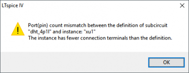
Thanks for this, but I still couldn't get it to work. I've attached the error msg I got.
I tried to make a symbol (.asy) for DHT_4P1L. I'm able to do this with the Ayumi and cogsnsnogs models, but I often can't get others to work.
This is the DHT_4P1L.asy file I made. It's probably riddled with mistakes.
* NOT WORKING - DO NOT USE
Version 4
SymbolType CELL
LINE Normal -48 0 -28 0
LINE Normal -20 0 -12 0
LINE Normal -4 0 4 0
LINE Normal 12 0 20 0
LINE Normal 28 0 36 0
LINE Normal 0 -48 0 -16
LINE Normal -20 -16 20 -16
LINE Normal -20 -12 20 -12
LINE Normal -20 -16 -20 -12
LINE Normal 20 -16 20 -12
LINE Normal 16 32 16 65
LINE Normal -16 33 -16 65
LINE Normal 1 24 16 32
LINE Normal -16 33 1 24
CIRCLE Normal -48 -48 48 48
WINDOW 0 8 -64 Left 0
WINDOW 3 62 -29 Left 0
SYMATTR Value 4P1L-T
SYMATTR Prefix X
SYMATTR Description This symbol is for use with a subcircuit macromodel that you supply.
SYMATTR SpiceModel DHT_4P1L.inc
SYMATTR Value2 DHT_4P1L
PIN 0 -48 NONE 0
PINATTR PinName P
PINATTR SpiceOrder 1
PIN -48 0 NONE 0
PINATTR PinName G
PINATTR SpiceOrder 2
PIN -16 64 NONE 0
PINATTR PinName K1
PINATTR SpiceOrder 3
PIN 16 64 NONE 8
PINATTR PinName K2
PINATTR SpiceOrder 4
--
Also, on this line in the sub file,
.SUBCKT DHT_4P1L 4_A2 1 2 3 4 ; P G K1 K2
Should I move the characters "P G K1 K2" so they come right after the SYMMATR Value2 ("DHT_4P1L")?
And what is "4_A2"?
--
Attachments
Last edited:
SUBCKT DHT_4P1L 4_A2 1 2 3 4 ; P G K1 K2
Use underscore everywhere!
DHT_4P1L_4_A2 with DHT_4P1L_4_A2.asy or delete 4_A2 subfix from name for using DHT_4P1L.asy.
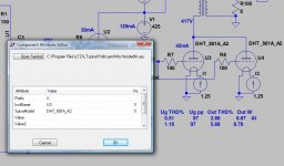
I generally use triodedht.asy, and manually edit (right click) component's SpiceModel attribute to actual name (in my example to DHT_801A_A2).
Attachments
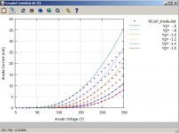
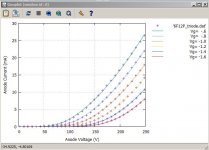
6F12P uTracer measurements
Earlier in the year I was sent a few 6F12P's by Bondini to measure.
For all the tubes, I found the variation to the data sheet to be considerable, for both the triode and pentode sections. Generally emission was significantly lower.
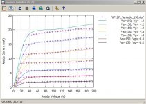
I have attached the files and sample curve matches (pentode Vg2=150V).
Note the deviation in the triode section above 10mA. Also be aware that mu had to be set to an unrealistic high value to get a good curve fit. I have not tried this in a circuit simulation.
Looking for Spice model of 6F12P (6Ф12П) both Triode and Pentode;
Earlier in the year I was sent a few 6F12P's by Bondini to measure.
For all the tubes, I found the variation to the data sheet to be considerable, for both the triode and pentode sections. Generally emission was significantly lower.
I have attached the files and sample curve matches (pentode Vg2=150V).
Note the deviation in the triode section above 10mA. Also be aware that mu had to be set to an unrealistic high value to get a good curve fit. I have not tried this in a circuit simulation.
Attachments
Hmm... My favorite tubes are being discussed finally... ;-)
12HL7, 6Ф12П, 4П1Л
I have developed models for 12HL7 as well as 6Ф12П (triode and triode-strapped pentode) in addition to the 4П1Л. I will share them when I get the chance
cheers
ALe
Update to 6F12P uTracer models
Apologies, I have now used a more recent version 3.0 of Derk Reefman's extractmodel which gives a better match and more realistic parameter values for the triode section (but measurements remain quite off the manufacturer's)
Note the deviation in the triode section above 10mA. Also be aware that mu had to be set to an unrealistic high value to get a good curve fit. I have not tried this in a circuit simulation.
Apologies, I have now used a more recent version 3.0 of Derk Reefman's extractmodel which gives a better match and more realistic parameter values for the triode section (but measurements remain quite off the manufacturer's)
Attachments
- Home
- Amplifiers
- Tubes / Valves
- Vacuum Tube SPICE Models