WRT the Reefman's models, if you want to use his models, you need to include the generic triode, pentode, etc. codes along with the specific parameters of the tube model, otherwise they don't work.
WRT to noise modeling, none of the commonly available models deals with noise, if you want to have it, then you need to add the required codes to the models yourself. But it is probably easier if you just add the noise sources externally as Merlin has done in his simulations, since you can tweak them on the fly, without editing the tube SPICE models themselves.
WRT to noise modeling, none of the commonly available models deals with noise, if you want to have it, then you need to add the required codes to the models yourself. But it is probably easier if you just add the noise sources externally as Merlin has done in his simulations, since you can tweak them on the fly, without editing the tube SPICE models themselves.
Last edited:
WRT the Reefman's models, if you want to use his models, you need to include the generic triode, pentode, etc. codes along with the specific parameters of the tube model, otherwise they don't work.
Thanks.
Does the generic tube model come first in the text macro file and then followed by the specific parameters, or the other way around, or does it matter?
WRT to noise modeling, none of the commonly available models deals with noise, if you want to have it, then you need to add the required codes to the models yourself. But it is probably easier if you just add the noise sources externally as Merlin has done in his simulations, since you can tweak them on the fly, without editing the tube SPICE models themselves.
I can't do that in Tina because it won't allow more than one source. Oh well. Thanks anyway.
This article:
http://www.ti.com/lit/an/snoa247b/snoa247b.pdf
talks about adding a noise source to their opamp models. The noise voltage stage is a diode in series with a resistor biased in parallel by a 0.1V voltage source. I tried it but ran into trouble.
Attachments
Last edited:
In TINA TI there may be another way, but the easiest I've found is to combine the two into one subcircuit.Does the generic tube model come first in the text macro file and then followed by the specific parameters, or the other way around, or does it matter?
For example:
Code:
****************************************************
* Connections
*                Plate
*                | Grid
*                | | Cathode
*                | | |
.SUBCKT ECC83_uT 1 2 3
* ExtractModel V .998
* Model created: 09-Dec-13
+ PARAMS: MU=108.93 EX=.988 KG1=389.8 KP=677.7 KVB=10751. RGI=2000
+ CCG=1.6P CGP=1.6P CCP=0.33P
RE1 7 0 1G
E1 7 0 VALUE=
+{V(1,3)/KP*LOG(1+EXP(KP*(1/MU+V(2,3)/SQRT(KVB+V(1,3)*V(1,3)))))}
G1 1 3 VALUE={0.5*(PWR(V(7),EX)+PWRS(V(7),EX))/KG1}
RCP 1 3 1G ; TO AVOID FLOATING NODES IN MU-FOLLOWER
C1 2 3 {CCG} ; CATHODE-GRID
C2 2 1 {CGP} ; GRID-PLATE
C3 1 3 {CCP} ; CATHODE-PLATE
D3 5 3 DX ; FOR GRID CURRENT
R1 2 5 {RGI} ; FOR GRID CURRENT
.MODEL DX D(IS=1N RS=1 CJO=10PF TT=1N)
.ENDS ECC83_uTYou need paint_kip.jar for tetrodes/pentodes.How does one generate tetrode/pentode models from curves? I usually use Paint_kit for triode models, but I don't see an option for pentode...
Model Paint Tools: Trace Tube Parameters over Plate Curves, Interactively
Scroll down to the bottom of the page.
In TINA TI there may be another way, but the easiest I've found is to combine the two into one subcircuit.
Thanks! I'll give them a try. That one compiled just great.
I can't do that in Tina because it won't allow more than one source. Oh well. Thanks anyway.
That's odd, I have not used TINA for awhile, but I thought you can have many sources in the circuit - it's one of the basic features of SPICE.
That's odd, I have not used TINA for awhile, but I thought you can have many sources in the circuit - it's one of the basic features of SPICE.
Maybe it's because I have the free version? I don't know.
Can you please check again, I don't think the free version has a limitation on the number of sources in the circuit... Also you might be interested in this.
I meant "inputs", not "sources". Sorry.
Merlin had suggested putting a current generator set to 2nA sine wave in parallel with each tube. Tina sees those as inputs and objects.
I'm searching for a reliable model of the 5902 penthode. I already found a model but looking ant the curves that comes out from the simulation they are wrong. This is what I have:
.SUBCKT X5902 A S G K
Bat at 0 V=0.636*ATAN(V(A,K)/12)
Bgs gs 0 V=URAMP(V(S,K)*0.19+V(G,K)+V(A,K)/40)
Bgs2 gs2 0 V=(V(gs)**1.58)
Bcath cc 0 V=V(gs2)*V(at)
Ba A K I=0.7E-3*V(cc)
Bscrn sc 0 V=V(gs2)*(1.1-V(at))
Bs S K I=0.4E-3*V(sc)
Bg G K I=(URAMP(V(G,K)+1)**1.5)*50E-6
Cg1 G K 7.5p
Cak A K 8.5p
Cg1a G A 0.2p
.ENDS X5902
I'm using LTSPICE
6N14P/ECC84
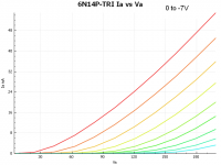
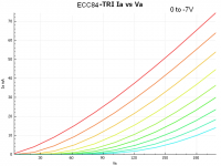
Some preliminary curves and tube models for the 6N14P and ECC84. The models and curves were generated in uTgui and represent the performance of a single section each of an unselected bogey device. I will post additional models when I have sense of what a representative device looks like parametrically.
Note that you need the generic Koren triode model in your library to use these. (Get from the uTgui site)
* n* library format: LTSpice
* Traced by Kevin Kennedy 2014-04-18 in uTgui
* Unselected sample
.SUBCKT 6N14P-KK 1 2 3 ; P G C (Triode) ; TRIODE SECTION
X1 1 2 3 TRIODE MU=26.21 EX=1.73 KG1=1196.1 KP=121.51 KVB=244.8 VCT=0.00 RGI=2000 CCG=2.8p CPG1=1.9p CCP=1.0p ;
.ENDS 6N14P
* n* library format: LTSpice
* Traced by Kevin Kennedy 2014-04-18 in uTgui
* Unselected sample
.SUBCKT ECC84-KK 1 2 3 ; P G C (Triode) ; TRIODE SECTION
X1 1 2 3 TRIODE MU=20.08 EX=1.42 KG1=705.7 KP=569.16 KVB=456.3 VCT=0.00 RGI=2000 CCG=2.8p CPG1=1.9p CCP=1.0p ;
.ENDS ECC84-KK
Something to note that these models were built from measurements on unselected samples and probably represent relatively large divergences in performance from the "typical" tube of this type. Use at your own risk.
Attachments
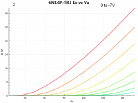
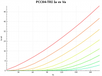
Here is a second 6N14P and a PCC84. I changed the plot from nine grid voltage plots to 8, 0 to -7V in 1V intervals.
The PCC84 actually measured closest of any of the devices I have measured so far to the measured operating conditions of the 6N14P in my latest phono stage design. (I selected them out of a dozen I have on hand)
Note that you need the generic Koren triode model in your library to use these.
Something to note that these models were built from measurements on unselected samples and could represent relatively large divergences in performance from the "typical" tube of this type. Use at your own risk.

* n* library format: LTSpice
* Traced by Kevin Kennedy 2014-04-18 in uTgui
* Unselected sample
.SUBCKT 6N14P-KK2 1 2 3 ; P G C (Triode)
X1 1 2 3 TRIODE MU=26.41 EX=1.80 KG1=1428.1 KP=146.35 KVB=244.0 VCT=0.00 RGI=2000 CCG=0p CPG1=0p CCP=0p ;
.ENDS 6N14P-KK2
* n* library format: LTSpice
* Traced by Kevin Kennedy 2014-04-18 in uTgui
* Unselected sample
.SUBCKT PCC84-KK 1 2 3 ; P G C (Triode)
X1 1 2 3 TRIODE MU=25.24 EX=1.38 KG1=658.8 KP=1065.54 KVB=474.6 VCT=0.00 RGI=2000 CCG=0p CPG1=0p CCP=0p ;
.ENDS PCC84-KK
The PCC84 actually measured closest of any of the devices I have measured so far to the measured operating conditions of the 6N14P in my latest phono stage design. (I selected them out of a dozen I have on hand)
Note that you need the generic Koren triode model in your library to use these.
Something to note that these models were built from measurements on unselected samples and could represent relatively large divergences in performance from the "typical" tube of this type. Use at your own risk.
* n* library format: LTSpice
* Traced by Kevin Kennedy 2014-04-18 in uTgui
* Unselected sample
.SUBCKT 6N14P-KK2 1 2 3 ; P G C (Triode)
X1 1 2 3 TRIODE MU=26.41 EX=1.80 KG1=1428.1 KP=146.35 KVB=244.0 VCT=0.00 RGI=2000 CCG=0p CPG1=0p CCP=0p ;
.ENDS 6N14P-KK2
* n* library format: LTSpice
* Traced by Kevin Kennedy 2014-04-18 in uTgui
* Unselected sample
.SUBCKT PCC84-KK 1 2 3 ; P G C (Triode)
X1 1 2 3 TRIODE MU=25.24 EX=1.38 KG1=658.8 KP=1065.54 KVB=474.6 VCT=0.00 RGI=2000 CCG=0p CPG1=0p CCP=0p ;
.ENDS PCC84-KK
Attachments
I'm searching for a reliable model of the 5902 penthode. I already found a model but looking ant the curves that comes out from the simulation they are wrong. This is what I have:
If you have the triode connected Ea-Ia curves for 5902 or EL71, I could build the pentode model for you.
If you have the triode connected Ea-Ia curves for 5902 or EL71, I could build the pentode model for you.
here it is

- Home
- Amplifiers
- Tubes / Valves
- Vacuum Tube SPICE Models