andrei said:Just so Mac users do not feel neglected, I have compiled MacOS X binaries (download them from http://sourceforge.net/projects/curvecaptor/).
Thanx, downloaded & i'll give it a spin when i surface for air.
dave
ngspice and pentode
Hi Andrei,
I have just downloaded your program. Very well done, it look to be very usefull.
It is some discussion about PARAM in pspice. I am using ngspice under linux, is it based on spice3f5, ciber1b1 and xspice with a few ameliorations. Among them, the numparam that extend the spice syntax and the use of subcircuit in a similar way as the pspice PARAM.
You can get it at http://ngspice.sourceforge.net/
It is a part of the Geda project, a full GPL'd suite of Electronic Design Automation tools:
http://www.geda.seul.org/
I know at some peoples have succesfuly installed those software on windows and mac, but it is simpler to install and use linux. It is the good opportunity to try linux if you don't have it.
Ngspice is fully capable without limitation as with the demo version of pspice. It is possible with it to use more elaborated models as the usual models we can find on the net, or/and to simulate a complete amplifier with the alimentation, the input source and the loudspeaker.
My main concern with audio tubes is guitar amplifiers. They are working in a very different way as in an Hifi amplifier.
We can get saturation from the input of the first tube (the voltage picks of my favorite guitare, an old Framus, are more as 2 volt high) to the output. That implie at we get grid courant in all tubes, and very big variation on Ig2 of the output tubes.
All the models I have try are very bad to model Ig1 and Ig2 when the tube is in saturation.
In fact, it is a problem for the pentode even when modeling a hifi amplifier, because you have to change the model's parameters when Ig2 is changing. For that, you cannot do an exact simulation of a superlinear PP.
I have try to do my own models, but it is not a simple or little work. I have allready done some research on the pentode-tetrode model and I am back to the begining, because the complexity was becoming to high. I am using the 807 because I have many documentations from different sources on that tube.
I prefere the korel approch, the convergence is much better as with the Duncan model, at least with the kind of circuits I am using: classic triode based preamplifier circuit, pentode in triode mode for the driver and pentode in PP for the output, no feedback at all.
Andrei, you want to model the pentode in a future release after the 1.0. Have you allready do some work on the pentode model?
I see at you don't have any working email list on sourceforge. I am not a programer, but I can help for developping a better model.
I am aware of the ngspice project, however I prefer Spice OPUS . One of the problems I have with ngspice and LTspice is that, while they are fast, the build-in sine generators have so much distortion that they are pretty much useless for audio distortion analysis.
I have tried Rydel's triode grid current model, and it sort of works, but is not very precise, so I threw it out from the current release. Personally, I have less interest in pentodes, as high power output does not impress me, and distortion is much worse than triodes. But eventually, I will add the tetrode/pentode model support. Getting good fits might be harder, though... If you come up with something interesting, feel free to email me. Or post it here. (Curve Captor does have a mailing list, but it is announce-only.)
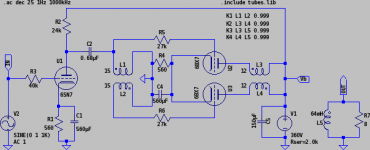
I am a little strapped for time right now. I have designed a neat little amplifier (6SN7-6BX7, single PCB construction, commodity parts, gets 5W without feedback) a while back using Curve Captor, but had not had a chance to build it (which is outrageous, as I even have the PCBs made). Once I test it, and if nothing explodes, I'll promote Curve Captor to 1.0, and get on to further development...
I have tried Rydel's triode grid current model, and it sort of works, but is not very precise, so I threw it out from the current release. Personally, I have less interest in pentodes, as high power output does not impress me, and distortion is much worse than triodes. But eventually, I will add the tetrode/pentode model support. Getting good fits might be harder, though... If you come up with something interesting, feel free to email me. Or post it here. (Curve Captor does have a mailing list, but it is announce-only.)
I am a little strapped for time right now. I have designed a neat little amplifier (6SN7-6BX7, single PCB construction, commodity parts, gets 5W without feedback) a while back using Curve Captor, but had not had a chance to build it (which is outrageous, as I even have the PCBs made). Once I test it, and if nothing explodes, I'll promote Curve Captor to 1.0, and get on to further development...
Attachments
Dmitry Nizhegorodov have done a java prgram to shearch tubes parameters, but Andrei's program is much better.
http://www.geocities.com/dmitrynizh/tubeparams_applet.htm
Dmitry have a program with the pentode model: http://www.geocities.com/dmitrynizh/tubeparams_image.htm
It is a try and retry program. It is very hard to find good parameters with it, but in the pentode case, it is very usefull to visualy find what is wrong. For exemlel, you run the pentode model, find good parameters, change Ug2, and yours parameters doesn't fit anymore. The consequence is at we cannot use a such model with anothing else as a fixed Ug2, and we have to recalculate-verify the model each time we change Ug2. It is not a realistic model for me, even if in a guitar amplifier I precisely use fixed Ug2. I can't do anything else, and that's the problem.
Another issue is to model Ig1 and Ig2. After my first rechearch, I was thinjing to try to use a modified diode model. But it will take some time...
Another issue is the reliablity of the model. And the reliability of the data sheets. For the 807, I have 2 completes sets of curves, one from philips and the other one from GE.
If the philips Ig2=f(Ua) curves are very good, they don't tell a lot about Ig2 when Ua is becoming very little. With the GE curves, they tell everything about Ig2 when Ua is becoming very little, but they are not so reliable (I have found some points where Ig2 is higher when Ug2=250V as when Ug2=300V).
I believe at the tube was becoming too hot when they have done this mesument. It is a point at Ua=0, Ug2=300V and Ig2=0.3A => Pg2=90W !!! when the CCS Wg2 is max 3.5W. It would be interesting to do such mesure with a modern equipment, but unfortunatly, I don't have such equipment.
Maybe the biggest challenge to have a class B pentode-tetrode PP that have a good sound is to have a power supply that can remain stable with the variations of Ig2, and where the g2 are not becoming too hot. The gain of the PP will change with Ug2, and it greatly improve the dynamic to have Ug2 that is stable.
It is not so hard with 2xEL34 or 807, but if you want more power and use more tubes, you have to considere a stabilisation at least for Ug2. And even for 2 tubes, a stab will greatly improve the dynamic and the overall sound. But be aware, if the Ug2 are becoming to hot, the tubes can explode. It append to me with my first prototype, it was a very expensive test... Now, I always put a fuse (and not a resistor) in the cathode circuit of my output stages.
I know at it is a conflict between the triode and the pentode guys. Personnaly, I like both. Triodes are great in hifi if we don't want to compromise the sound, but tetrodes are great to made a compact amplifier or a guitar amplifier. If it would be possible to do a class AB1 or even class A guitar amplifier for a jazz musician, class B is much better for a blues or rock player.
If we look at the history, the guys that have done the first triodes have done a very good job. After with the tetrode, it was not possible to get a good sound. It have become better with the pentode, and with the last tubes, the beam power tetrode, we have a tube that have the most of the advantages of both triode and pentode, a great sensibility and a low output impedance.
It is possible with a beam tetrode to archieve very good results. You must have, as with the triode, a perfect symmetry in the driver and in the output transformer, and a good power supply. In case of very high power amplifiers, the main problem is at the power supply is fast becoming far more complicated as the amplifier, because you must use stabilisation and have electronic current securities. In practice, for a big sonorisation, it is far better to use many amps as a very big one.
The best tetrode to me are those between a few watts to 25-30 watts Pa. It is more powerfull tubes on the market, but they don't have a good sound.
Power is one thing, but dynamic and distortion is another thing. If it is possible to archieve 100W at the output with 2 EL34 or 807 in class B, but the sound will be much better at 60-70 watts in class B, or 25-35 watts in class AB1.
I have done a guitar amp with 2xECC83, 1xEL84 in triode and 2x807 in PP class B. The sound is so great at I can use a hifi loudspeaker with it at the place of the medium loudspeaker they call "guitar loudspeaker". I have no simulation for it because I have done the development on the paper and on the prototype. With a bass at the input, the guitar loudspeaker from a Peavey Mace was just doing like a fan, a ventilator. And with a little bigger driver and output transformer, I am sure at the sound would be even better for a bass player..., with an appropriate loudspeaker.
A friend have made almost the same amp with 2xEL34, and a bassreflex loudspeaker, for a bass player. I tested it, it was like an engine of plane in the room.
How do I install Curvecaptor in Windows ?
I have downloaded the file curvecaptor-0.9.1-winxp.zip, and I get the files curvecaptor.tcl, m4.exe, models.m4, readme.txt, and tubefit.exe. I have read the readme file, but I do not understand it. It says to edit and run the Make file. What or where is that ?
When I run the exe files all I get is a blank DOS window.
Have I got the right files ? How do I get this thing to actually work ?
You need Tcl/Tk to run the GUI - get it from ActiveState. Then run the curvecaptor.tcl (if you did associations properly when installing Tcl/Tk, you'll just need to double-click it). Read this thread for more info.
'make' is a build tool of Unix origins. It is used for automatic compilation of source code. You don't have to do anything, though, as you already have the binary distribution.
'make' is a build tool of Unix origins. It is used for automatic compilation of source code. You don't have to do anything, though, as you already have the binary distribution.
thanks, and 2 more questions
Andrei :
Thanks, I've got it up and running now. Its a lot faster than fooling around with the spreadsheet I use now.
But I have 2 questions I dont see addressed in this thread.
1) I have loaded your sample 6SN7 gif file, and have used curvetracer to put on the Vp markers, Ip markers and the data markers. But how do I convert that into actual data to build a model ? On the screen shot of the curvetracer mode in one of your first posts there are a bunch of buttons at the bottom of the screen, one of which is "capture curve" This sounds like what I want, but I dont see it on my screen. Is it missing from the Windows version or am I not doing something correctly ?
2) I am having trouble getting it to work with both positive and negative grid voltages in the same set of data. I can get it to show curves for -ve grid voltages
eg 0, -2, -4, -6,
or curves for +ve grid voltages
eg 4, 2, 0,
but not for both,
eg 4, 2, 0, -2, -4, etc
Is there some specific order I need to sort the input data in ?
I realize +ve grid voltage is normally avoided in audio amplifiers, so this is not a huge issue.
Andrei :
Of course, I am a dough head ! I had to resize my window and then pull up the bottom. Are there any windows experts out there with ideas how to have the window open in the "correct" size, ie the program window size not bigger than the screen ? Its only a minor inconvenience but I just wonder if there is some way of not having to do this.
Also, is there any advantage to putting Vp and Ip markers on Both sides of the graph ? Will doing that compensate for any crookedness in the gif graphics or will it just confuse the program ?
Enjoy your hike, I will play with the program some more in the meantime, and perhaps answer my own questions.
additional information for =ve grid voltage problem
I ran some tube data, with positive grid voltages included, through the program once with the +ve grid data points first, and then again with the +ve grid data points last. I also ran the data through my excel spread sheet, and in all three cases I came up with the same model parameters, at least the same for the first 5 or 6 decimal places. So curvetracer handles the +ve grid voltage data correctly. It is only the graphing which is a bit odd. If I list the +ve grid data first it graphs the highest value +ve grid voltage line, and the 0 grid line, and that is all. If I list the -ve grid voltage data first then it draws the 0 grid line, and all the -ve grid lines, but none of the +ve grid lines.
Since it is generating the correct model parameters, and since I export the results to spice and work with them there anyway, this graphing of +ve grid voltages issue is not a show stopper for me.
Work very fine but...
I'm using the demo version of Microcap, and this is my first experience in simulation!
Now, i've just generated my first model (6BX7GT), using the "Pspice" and "Koren8" setting as output i've obteined this:
* 6BX7GT PSpice model
.subckt 6BX7GT P G K
Gp P K VALUE={(0.1010275246m)*limit(V(P,K)*log(1.0+(-0.1066002576)+exp((3.185240505)+(3.185240505)*((12.3114364)+(-26.35405875m)*V(G,K))*V(G,K)/sqrt((11.17415062)**2+(V(P,K)-(-5.770011549))**2)))/(3.185240505),0.0,1.0e16)**(1.443542621)}
.ends 6BX7GT
Seem to be ok, but...what about the interelectrodic capacitances?
How i can implement Cgp, Cgk and Cpk in the code?
Many thanks!
With something as:
Cgp G P <value>
Cgk G k <value>
Ckp K P <value>
where <value> is the value of the capacitance, as exemple 9pF for 9 picofarad.
I suggest you to read this page, especialy the Interactive User Guide and the user manual
http://bwrc.eecs.berkeley.edu/Classes/IcBook/SPICE/
Microcap (MC) can differ in some points, so you have to read MC documentation too.
Dominique_free said:With something as:
Cgp G P <value>
Cgk G k <value>
Ckp K P <value>
I've just tried this way but the simulation is not reliable...
The source sees a load equivalent to the Cgp value, Miller effect seem to be missed!
Many thanks for the link!
The declarations for the capacitance must be in the subcircuit, that mean between the lines .subckt and .ends
I use most ngslpice and don't have problem with the miller capacitance with it. In the past when using windows at home, it was no problem with microcap. Maybe it is a syntax problem. Pspice syntax is not always the same as spice syntax, and especialy with subcircuits. I don't remember if microcap can use both syntaxes.
Another soft that run both on windose and linux is LTspice. I don't like the shematic part but the simulation part is better as microcap, and its free software without limitation. http://www.linear.com/company/software.jsp
I successfully modelled the 5744, and on the off chance someone else will find it useful, here it is:
* 5744 macro model
.subckt 5744 P G K
rydel5(0.004301287345,0.0005306397292,55.85145507,-13.68310505,-17.57164766)
.ends 5744
* 5744 LTSpice model
.subckt 5744 P G K
Bp P K I=((0.004301287345m)+(0.0005306397292m)*V(G,K))*uramp((55.85145507)*V(G,K)+V(P,K)+(-13.68310505))**1.5 * V(P,K)/(V(P,K)+(-17.57164766))
.ends 5744
Use one or the other obviously depending on what version of spice you are using..
When using LT spice for transient response simulations keep maximum step size small in order to keep distortion of sine source in simulations small. I use 10nS - 100nS typically if I will run an fft on a transient simulation.
Results seem reasonable based on simulation of existing circuit.
- Status
- This old topic is closed. If you want to reopen this topic, contact a moderator using the "Report Post" button.
- Home
- Amplifiers
- Tubes / Valves
- Vacuum tube modeling software - beta testers wanted