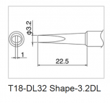
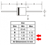
I bought some 3.2mm wide chisel-tips for heating up fat 5mm desoldering braid (Pro wick #6), to work on a PSU board that uses rectifier diodes in the massive R6 package. I find these tips work well both for soldering and desoldering, of huge diodes attached to whomping fat traces. Mine's the Hakko T18-D32.
Attachments
Build guide - still in progress.
Lots of good photos.")
http://www.diyaudio.com/forums/powe...circuit-board-v3-illustrated-build-guide.html
Lots of good photos.
http://www.diyaudio.com/forums/powe...circuit-board-v3-illustrated-build-guide.html
Stupid question... Do you need to reverse polarity(secondary winding) of one the secondaries to get a "central tap" — ground in phase? I mean begging of one secondary to AC1A, but end of the second secondary to AC2A. If using Antek 1st blue to AC1A, but 2nd green to AC2A.
You have 2 secondaries, green-blue, green-blue.
The 1st green will be the lead winding
you will tie the 1st blue to the 2nd green, that becomes your centertap.
2nd blue will become your trail (end) winding.
Essentially you just tie the middle wires together to make the centertap.
The 1st green will be the lead winding
you will tie the 1st blue to the 2nd green, that becomes your centertap.
2nd blue will become your trail (end) winding.
Essentially you just tie the middle wires together to make the centertap.
Yes.
You only need one bridge. Not two.
Break them both off and use one, the output of that bridge will attach as follows -
Diode board V+ will attach to Cap board D+1
Diode board V- will attack to cap board D-2
The C.T. will attach to D-1 and D+2, and you will also need to connect D-1 and D+2 to make GND. (The PSU board has no connection to make GND, as there is the break-apart seam where the copper would be...)
need help on wiring
Hi everyone, appreciate some help on my power supply board.
I've purchase 2 x universal power supply circuit board for my honey badger amp with an intention of wiring it up in dual mono configuration like Jojo did in his guide.
The transformer i'm using is a 500va with 2 sets of secondary (0-40v blk yel, 0-40v blk yel)
As per Jojo's guide and the final picture, i wire the transformer secondary to the 2 boards in this manner.
1st board:
Yel(1st pair) to AC1A and Blk(1st pair) to AC1B
Yel(2nd pair) to AC2A and Blk(2nd pair) to AC2B
2nd board:
Jumper AC1A to 1st board's AC1A spare hole
Jumper AC1B to 1st board's AC1B spare hole
Jumper AC2A to 1st board's AC2A spare hole
Jumper AC2B to 1st board's AC2B spare hole
Upon powering up, the 4 power resistor of the softstart board immediately smoke out forcing me to power down immediately.
Did some check on the PSU board, soft start board and found no issues or shorts. So i went on to try powering up just 1 PSU board instead of 2 by removing all the jumpers to another board. Upon powering up, the psu led came on and it remains stable without any smoke. Did some voltage check on the output with dmm turns out to have + voltage on each side of the board. But base on the checklist, it should have + and - voltage reading.
Tried various jumper configuration but always ended up with a smoke resistor in the soft start board.
Am i doing anything wrong? Seems like the only difference i have from Jojo's guide is the transformer. Could it be the transformer that is giving me problem or i've mess up wirings somewhere. Appreciate some advice on this problem. Thanks in advance.
don't mix up these wires. Check with a resistance or continuity meter and label them as winding1 and winding2............The transformer i'm using is a 500va with 2 sets of secondary (0-40v blk yel, 0-40v blk yel)........
Similarly if the primary is dual windings.
Power up via a mains bulb tester to prevent you destroying a new but miswired transformer.
tested
Hi AndrewT,
The primary has 3 wires. 0-120v-240v (blk,blue,red). Connected blk and red and safety kept the blue. It works fine and powers up.
Secondary side, have checked with dmm with each winding correctly giving out close to 40vac. When power up one side of the board through the psu board it's rectified to about 58 vdc.
It's just that I couldn't manage to get both psu board to fire up without smoking the soft start board 5w power resistors no matter how I jumper them. Or do I need to buy another transformer? And how can I get a negative 58vdc.
Thanks for advice.
Hi AndrewT,
The primary has 3 wires. 0-120v-240v (blk,blue,red). Connected blk and red and safety kept the blue. It works fine and powers up.
Secondary side, have checked with dmm with each winding correctly giving out close to 40vac. When power up one side of the board through the psu board it's rectified to about 58 vdc.
It's just that I couldn't manage to get both psu board to fire up without smoking the soft start board 5w power resistors no matter how I jumper them. Or do I need to buy another transformer?
And how can I get a negative 58vdc. Thanks for advice.
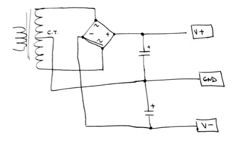
Each 40Vac winding when you bridge rectify, each will give your required 58Vdc.
Just connect the DC outputs from the two bridge rectifiers in series. That series will give you 0Vdc, 58Vdc, 116Vdc, if you connect one end as your reference.
If you connect your reference to the other end you get: 0Vdc, -58Vdc, -116Vdc.
If you connect your reference to the middle you will get: -58Vcd, 0Vdc, +58Vdc
Just move the reference to a different tapping and you get any of those voltage arrangements.
Alternatively:
Series connect the two 40Vac windings to give 80Vac, with a centre tap at 40Vac.
Bridge rectify the 80Vac and feed to a series pair of smoothing capacitors. Connect the centre tap at the transformer to the common between the capacitors.
You now have 0Vdc, 58Vdc, 116Vdc.
You can move the reference around as with the dual rectifier version to get the voltages that you need.
Last edited:
Some improvements
Thank you AndrewT,
After your post, i fiddle with the output configurations and manage to get 1 transformer secondary to power-up 1 psu board with 2 bridge by arranging in such a manner:
On the AC input side:
Transformer 1st secondary winding to AC1A/AC1B and jumper it over to AC2A/AC2B
On the DC output side:
V+ and Gnd 1 on one board and Gnd 2 and V- on another board.
Connected Gnd 1 to V- and wire it as reference which makes V+ the positive voltage and Gnd 2 as the negative voltage.
Both side of the psu board lights up and works fine with this configuration so i assume i can power both psu board this way by mirroring the configuration on another psu board.
But my question is, with this DC output configuration am i getting a +58 0 -58? or im getting a +58 0 +58.
DMM check with positive probe to V+ and negative probe to Gnd 1 shows a positive +58 vdc. With positive probe to Gnd 2 and negative probe to Gnd 1 also shows me a positive +58 vdc. Or am i measuring it wrongly that i should positive probe the Gnd 1 and negative probe the Gnd 2?
Afraid to plug those wires into my honey badger board before making sure and clear. Appreciate some advice. Thank you.
Any updates with availability? Thanks!
I'd estimate 3 weeks to shipping out date.
Is there any chance I can get a part of my order to be shipped? I will pay the shipping. They are a pair of ACA pcb's.
If you have an order that's being held up by a pre-order item, yes you can have the order split (and pay the difference for shipping). Just contact the helpdesk at diyAudio | Portal with your order number and all the details and Elena will fix you up.
measure from Zero Volts to Voltage. Then Zero Volts to other Voltage.Thank you AndrewT,
After your post, i fiddle with the output configurations and manage to get 1 transformer secondary to power-up 1 psu board with 2 bridge by arranging in such a manner:
On the AC input side:
Transformer 1st secondary winding to AC1A/AC1B and jumper it over to AC2A/AC2B
On the DC output side:
V+ and Gnd 1 on one board and Gnd 2 and V- on another board.
Connected Gnd 1 to V- and wire it as reference which makes V+ the positive voltage and Gnd 2 as the negative voltage.
Both side of the psu board lights up and works fine with this configuration so i assume i can power both psu board this way by mirroring the configuration on another psu board.
But my question is, with this DC output configuration am i getting a +58 0 -58? or im getting a +58 0 +58.
DMM check with positive probe to V+ and negative probe to Gnd 1 shows a positive +58 vdc. With positive probe to Gnd 2 and negative probe to Gnd 1 also shows me a positive +58 vdc. Or am i measuring it wrongly that i should positive probe the Gnd 1 and negative probe the Gnd 2?
Afraid to plug those wires into my honey badger board before making sure and clear. Appreciate some advice. Thank you.
Now measure from Voltage to other Voltage.
If your supply is +58,0,-58, then the three readings will be +58, -58, +116
If your supply is +58,0,+58, then the three readings will be +58, +58, +~0
Have you fitted Rail to Ground diodes on the amplifier?
Have you fitted Rail to Output diodes on the amplifier?
Have you built up and used the Mains Bulb Tester?
If you have done all three, then you will not damage the amplifier.
- Home
- The diyAudio Store
- V3 Universal Power Supply Circuit Board