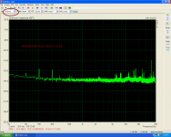
I haven't any low distortion source. I use sound card line out as freq. generator and amplifiers output via voltage divider to the sound card line in .In this case common gnd is more important! When i want to see noice figure i manage to connect amplifier's output only to line in.Using ARTA i adjust sig to External. Always i run three test. The first with shorted input.(see picture). Second with open input. Third with input connected to a source but no signal. The same set test using a scope.
Attachments
Last edited:
Some PS supply boards available from prashi.
Only 4 caps per channel not 6 or 8 but still good and high quality
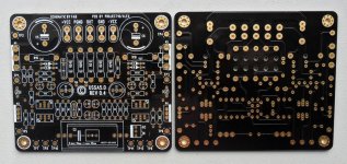
CRC Power Supply (Class A amplifier)
Only 4 caps per channel not 6 or 8 but still good and high quality
CRC Power Supply (Class A amplifier)

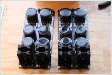
For USSA-5 supply voltages you can have up to 136000uF per rail with 5-leg capacitors.
5-Pin Elko Kondensator 68000mF 35V 85degC ; ESMH350VQT683MB80T ; 68000uF
")
I didn’t want to hijack your thread but I posted another build and review on the USSA-5 here: http://www.diyaudio.com/forums/solid-state/324275-ussa-5-build-review.html#post5471835.
Hi Lukehi Fab, I would like to bridge these amps. I am thinking 1.2A per fet, with 23V rails. Do you see any problem with this configuration? Maybe one day biamp, but I struggle to build the same amplifier twice
Frankly I have never thought about bridging any amp so far. I never saw the interest (but I can be wrong also) since to get 4 times the theoretical power you need anyway a bigger PSUnd especially for class A...
in this case the price of Mosfet makes is expensive anyway to go bridge.
Biamplification seems appropriate if needed. But I suggest you build one first to get a feel before investing in 2 amps... biamplification with 2 same amps is more efficient if the crossover corner frequency is optimized for equal distribution of power. See Elliott sound site for info.
Fab
Some PS supply boards available from prashi.
Only 4 caps per channel not 6 or 8 but still good and high quality
CRC Power Supply (Class A amplifier)
Project16 designed those CRC boards with USSA-5 "in particular" and other /any class A/AB amps "in general". Post # 1 of "CRC Power Supply (Class A amplifier)" thread gives the info.
Like he posted, mammoth capacitance can be fitted along with normal to-220 or to-247 diodes
. Also many options for resistors. In short a universal design.Hi
Between +/-23 and 28vdc.
Output Bias between 1A and 1.4A. THD curves shown at post 108 and 116 with amp at 1.2A and PSU of +/-23.5vdc.
This is a "typical " PSU/heatsink requirement for most 20-25wrms class A amps into 8ohms.
For the same heatsink, if you have 4 ohms speakers you can also lower the PSU voltage and increase the bias proportionally to stay in class A at higher power.
Fab
Last edited:
Hello everyone
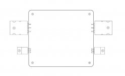
I have at disposal the drilling gabari to carry out a clean and precise work on the heatsinks.
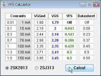
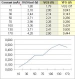
I also for those who would like to measure transistors drivers without going through the calculation phase a small program (Win) and a spreadsheet.
I have at disposal the drilling gabari to carry out a clean and precise work on the heatsinks.
I also for those who would like to measure transistors drivers without going through the calculation phase a small program (Win) and a spreadsheet.
Attachments
Group buy moved to Group buy section
Hi
It appears that the posts related to the specific group buy of the USSA-5 pcb has been moved by a forum administrator here:
USSA-5 PCB GB
Thanks to follow this link.
Fab
Note to admin: some direct insults have been done to me and they are still in this thread so can you check if you can do a clean-up about that...
A moderator can send me a PM if required.
Last edited:
Hi,
Just an update, I ordered from Profusion and they sent me the P (ECW20P20-S) and N channel (ECW20N20-S) pairs in 1 week to the US! P channel is composed of an orange band matched pair while the N channel is composed of a yellow band matched pair. I requested red bands but oh well.
Maybe more second harmonic. Maybe not. Who knows?!
Best,
Anand.
Last edited:
- Home
- Amplifiers
- Solid State
- USSA-5 Build with Review