Torrent file can be downloaded from below link as well.
http://vicol-audio.ro/docs/Forum_Audiofil_Test_CD.6322268.TPB.torrent
Please note this CD contain test signals and may destroy your amplifier (overheating) or speakers, is not intended for listening.
I take no responsibility of inadequate use of this material.
Regards,
Tibi
http://vicol-audio.ro/docs/Forum_Audiofil_Test_CD.6322268.TPB.torrent
Please note this CD contain test signals and may destroy your amplifier (overheating) or speakers, is not intended for listening.
I take no responsibility of inadequate use of this material.
Regards,
Tibi
Last edited by a moderator:
This is a transport from a cheap boombox player. No matter what you do to it and how many fancy caps you put on it, it will still be a transport from a cheap boombox player.
This is a classic example of the kind of mass hysteria that grips audiofools so often.
An (audio)fool and his money are easily parted.
It was also used in mid range players such as the NAD-540, and NAD-541.
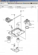
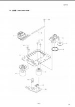
The service manuals are available on line and even though they use internal numbers, they translate to the SFP-101V laser assembly and DA11 series of transports.
So what makes the transport cheap? The fact that it was used in inexpensive boom boxes? This simply implies it is cost competitive and does not in itself say anything about quality.
Thus it is simply a cost optimized transport with a minimalist approach to the load mechanism (none) and other amenities which are added as marketing hype to convince consumers that they need the options on mid range and high end systems.
The specifications for the transport mechanism are available.
The main fault I can see with the Boom Boxes is they use the audio out instead of using digital out with a good D/A converter and use lesser quality components to support the drive. This all is in line with the marketing requirements.
So, how is the unit "cheap"? (Implying inferior quality)
What are the specifications of the DA11VZ which are of poor tolerance which will contribute to poor sound quality?
Since this design uses and external D/A, those analog specifications are not in question.
What are the specifications of the DA11VZ which are inferior?
On to high quality.
Top end players are to some extent hype. The remainder is quality design and manufacturing with high quality components.
Given that many mid range players can be upgraded to compete with high end players by replacing components with better tolerance and higher quality components, how is this different?
Show us the specifications for the transport in a high end system, and show where this unit is deficient and how that translates into poor audio.
Attachments
Last edited:
At this time almost all full Shiga kits have been shipped and my inbox is near to boom. 
Building Shiga from kit mean you have already some minimal electronics knowledge.
You need to know how to use a multimeter and how to measure a component.
You need to recognise components, to know which is which and how to set your multimeter in order to get accurate measurements results.
You need to have good experience and soldering skills.
You need to have proper tools in your lab:
- soldering station with temperature adjustment
- multimeter - resistance, capacitance, volt, amper, junction
You need to be able to measure components from the kit.
Where is possible these are marked, but some are so small and it is almost impossible for me to mark.
A cheap option is 72-8485 - TENMA - COMPONENT TESTER WITH TWEEZERS | Farnell United Kingdom
A profesional option is http://www.advancedevices.com
Please follow the BOM list and post general interest questions on forum so other may benefit from responses as well.
Please also note that not all the components from the BOM list must be into your full Shiga KIT.
Some are presented as an alternative (move mouse over the excel sheet to see comments).
Different components should be used up to the clocking configuration you chose. Also, diferent components should be used up to regulator you use (L7808 or LT1086 or LM317).
Read schematic carefully. We did our best to make this project a success, but you need to help yourself as well.
Thanks !
Regards,
Tibi
Last edited by a moderator:
Hey Gopher,
Please do us a favor and leave us alone to our hobby. Personally I don't appreciate your cynicism. I have built and have been listening to a shinga made from the JVC boom box and have been very happy with it. It sounds better than the NAD S500 (silverline) cd player that I paid $1500 for about 10 years ago. This opinion was confirmed through blind testing with my audiophile friends. Hmmm.. $1500 doesn't sound as good as $200. Hmmmm. You can be skeptical and of course you are welcome to ask questions, but please do us a favor and keep any opinions that we are fools to yourself. This is a hobby. I do this for fun. It is your prerogative to believe that building a cheap part into a good sounding piece of equipment isn't possible or likely, but please don't rain on the parade of those of us enjoying our hobby.
Please do us a favor and leave us alone to our hobby. Personally I don't appreciate your cynicism. I have built and have been listening to a shinga made from the JVC boom box and have been very happy with it. It sounds better than the NAD S500 (silverline) cd player that I paid $1500 for about 10 years ago. This opinion was confirmed through blind testing with my audiophile friends. Hmmm.. $1500 doesn't sound as good as $200. Hmmmm. You can be skeptical and of course you are welcome to ask questions, but please do us a favor and keep any opinions that we are fools to yourself. This is a hobby. I do this for fun. It is your prerogative to believe that building a cheap part into a good sounding piece of equipment isn't possible or likely, but please don't rain on the parade of those of us enjoying our hobby.
I will add this to what Tibi said with regards to assembly of the bare PWB.
I installed SM (Surface Mount) resistors first. This is for several reasons including (1) they are not nearly as static sensitive as some other parts (2) they are easy to verify when on the board, (3) once they are installed there is less chance of installing another component in the wrong position as half the positions are filled.
Next I install all of the SM Capacitors. Be extremely careful installing these as it is difficult to get accurate measurements of the values once they are installed.
Third I install the SM inductors/filters.
Up until now the components have not been extremely static sensitive. Resistors and capacitors can be damaged by ESD so one still needs to use a static strap, etc when installing ALL components.
From here on extreme diligence must be paid to the assembly as ESD sensitive components are handled. Some devices can be damaged by as little as 200V static discharge (human body model). Once on the PWB, the components are less sensitive, but the assembly should still be handled with care using static strap, etc.
Fourth I install the SM ICs. I use excessive solder and once the components are completely soldered I remove the excess with solder wick. I visually inspect and re-solder lightly if necessary. This procedure insures that solder wicks between the pad and leg of the IC. By excessive solder I don't mean big blobs, but enough to flow over the top of the IC leg, but not short to the adjacent leg in most cases.
Finally I install the through hole components in the order of (1) Connectors, (2) transistors, (3) Resistors, and finally (4) capacitors. This sequence is due to height and simply makes handling easier.
A good set of curved end tweezers is indispensable in holding SM components.
A temperature controlled fine tip soldering iron is a must for work with SM components.
Clean the assembly with 70% or higher Isopropol alcohol and a soft brush. I do this twice to be sure I've removed all flux, and other contaminants.
NOTE: Tantalum capacitors are very static sensitive. Handle them like transistors and ICS.
Hey Gopher,
Please do us a favor and leave us alone to our hobby.
+1. It might also be worth noting that Peter Daniel, who was one of the key DIY'ers who started this whole thing, used this same mechanism and a stock PCB (plus modifications) to create something that (in his comparisons) equalled or bested a ML 31.5 and CEC TL0. Peter has been around here long enough to show he's an honest broker.
Documentation still in work, but already contain relevant information for those who ordered DIY and Full Shiga KIT.
http://sdrv.ms/WZbPnw
Regards,
Tibi
I can't see that link ..you have to sign in to see it.
My bad to use a micro$oft product.
Back to real world https://docs.google.com/open?id=0B-QF0EAtUutecEdsTzZpRnd1OWs
Regards,
Tibi
Back to real world https://docs.google.com/open?id=0B-QF0EAtUutecEdsTzZpRnd1OWs
Regards,
Tibi
Tibi, in the user manual you state that U2 needs a heatsink. Yet in the mounted and tested version there is no heatsink. Do I need one?
Should work fine without one as well. We have designed PCB to dissipate a great amount of heat.
However, if you intend to mount Shiga in a closed box, than you may need a small heatsink. Solder two small copper plate in the holes near to U2 or fill these holes with solder. This will help heat dissipation to the top side of PCB.
Regards,
Tibi
All switching power supplies by their very nature generate a great deal of unwanted noise (EMI/RFI).
It is possible to minimize the noise escaping from a switching power supply, however it takes a great deal of effort and understanding about how they work, ground systems, etc.
The fact that you are asking if this device (or any other device for that matter) could be made into a 'good power supply' indicates you may not have sufficient understanding of the underlying noise sources to design a switching supply to meet the requirements.
I highly recommend you avoid a switching supply for any audio devices.
Perhaps interesting to report Mr. Jung's new shunt regulator, there is a book released where about 13 well-known regulators are tested measuring and listening test, someone already read this book?
Here you find "some info": http://www.diyaudio.com/forums/power-supplies/220734-mr-jungs-new-shunt-regulator.html
http://waltsblog.waltjung.org/
Regards,
Rudy
Here you find "some info": http://www.diyaudio.com/forums/power-supplies/220734-mr-jungs-new-shunt-regulator.html
http://waltsblog.waltjung.org/
Regards,
Rudy
Hi TheGimp
It is indeed that I have no undertanding about smps.
So just the simplicity of the fsdh321.
That a smps (can) generate nois I know.
But 2 points,
A smps of 20 years ago or more, or a smps of the present
Its almost not to compare.
And a few years ago I read fore the second time the review of
the linn cd 12, and was surprised that they used a smps.
The linn cd 12 is still one of best cd players ever made.
So they solved the nois problem.
I believe that that quality for diy is not possible.
I think that the question is how can we solve the nois in a
smps, instead of don't use a smps in audio.
Because I am sure that a lineair PS is not sufftcient to get
the best out of audio.
To anyone, please react, give your opinion, I hope as soon as
possible that we here can start for a real good PS. for a shiga clone.
Best regards
While the need to calculate loop stability and tailor a feedback loop to compensate are for the most part long gone, the innate switching characteristic of the switching power supply have not changed.
In fact, they have gotten worse as Rds-on of FETs is now down into the low m-Ohm range, and Turn-on / Turn-off times are greatly decreased.
These are what makes switching regulators difficult to use in audio applications.
The inductor needs to be well shielded to prevent radiated interference.
The ground system needs careful attention to prevent switching currents from imposing themselves on the output voltage via the ground resistance.
In addition the linked article is for a flyback regulator. The flyback topology is inherently noisy.
For multiple outputs the article states a larger core will be needed, thus dictating a lower switching frequency. With a switching frequency in the lower portion of the 50-134Khz range, you are likely to have inter-modulation artifacts in your audio.
Lastly is the transformer itself. Care need be taken to insure low leakage inductance or efficiency goes down along with the output.
I recommend reading AN4137 before proceeding as it steps through the design process.
The process will require a PCB as flying lead construction introduces too much stray capacitance and inductance. Although, those are minimized by the low switching frequency.
Guys I m starting to build my own based on the tested kit. I was wondering what people are using for the chassis.
I am planning to use a plank of 27mm wenge to make the entire chassis out of it. I have used it on my DAC and preamp and I really love it. Both for its looks and its damping properties (nice, dense and heavy wood).
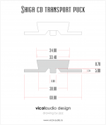
Any suggestions on how to mount the turntable for best results? I have checked how Peter did it and I am thinking of something similar but no copper plate. Full wenge everywhere.
I am planning to use a plank of 27mm wenge to make the entire chassis out of it. I have used it on my DAC and preamp and I really love it. Both for its looks and its damping properties (nice, dense and heavy wood).
Any suggestions on how to mount the turntable for best results? I have checked how Peter did it and I am thinking of something similar but no copper plate. Full wenge everywhere.
AL CD puck dimensions attached.
Documentation was updated page 6 (Tentlabs clock implementation).
https://docs.google.com/document/d/1vlabZc_1If3x12ox2A5ECZxC0HLGnuOWdM-j9X4b7Q0/edit
Regards,
Tibi
Documentation was updated page 6 (Tentlabs clock implementation).
https://docs.google.com/document/d/1vlabZc_1If3x12ox2A5ECZxC0HLGnuOWdM-j9X4b7Q0/edit
Regards,
Tibi
Attachments
Last edited by a moderator:
- Home
- Source & Line
- Digital Source
- Using the new 2012 Shigaclone to create a killer high end transport