I've never put up the BUF03 data sheet, so here it is. Still impressive, and zero feedback as well.
Cheers George
Maybe I'm missing something, what's so impressive besides the low offset?
FWIW, it uses local feedback around the OP stage, check the schematic
on data sheet.
")
Maybe I'm missing something, what's so impressive besides the low offset?
FWIW, it uses local feedback around the OP stage, check the schematic
on data sheet.
It may have local but no global, and this makes it to my ear better than any opamp output stages.
It sounds way better and punchier than the inbuilt buffer of the AD844 and the discrete buffer I tried and posted a pic and circuit of quite a few pages back.
Cheers George
George,
BTW. I don't know the input impedance of Pedja's buffer. In any case I don't use one, having tried both the inbuilt buffer and a discrete FET buffer (when I used to use the AD844) I prefered the sound without one, driving my 7k5 attenuator directly from pin 5, so I kept this arrangement with the discrete circuit. Surely the I/V resistor already loads down the output of the I/V section so I don't see any advantage of adding a buffer, particularly where very short interconnects are used...or am I missing something?
Incidentally, I null the dc offset by trimming (very slightly) the value of either of the 1K resistors which connects between the collector and base of the BC557/BC547.
Joe
Esgigt has posted the schematic.
Last edited:
George,
BTW. I don't know the input impedance of Pedja's buffer. In any case I don't use one, having tried both the inbuilt buffer and a discrete FET buffer (when I used to use the AD844) I prefered the sound without one, driving my 7k5 attenuator directly from pin 5, so I kept this arrangement with the discrete circuit. Surely the I/V resistor already loads down the output of the I/V section so I don't see any advantage of adding a buffer, particularly where very short interconnects are used...or am I missing something?
Incidentally, I null the dc offset by trimming (very slightly) the value of either of the 1K resistors which connects between the collector and base of the BC557/BC547.
Joe
Esgigt has posted the schematic.
Let me get this right, your driving the TZ output into a 7.5kohm attenuator, which in turn drives your amps? What value TZ resistor to ground are you using and what cap?
Cheers George
Let me get this right, your driving the TZ output into a 7.5kohm attenuator, which in turn drives your amps? What value TZ resistor to ground are you using and what cap?
Cheers George
That's correct. The output is DC coupled to the attenuator and the I/V resistor is around 2k7. With my TDA1541A DAC the output voltage is slightly higher than normal but my JLH amp has a lowish gain and my ESL-63s need some juice. Even with the 'smoother' sounding 2SA/2SC devices the discrete I/V is not short on dynamics. For example with no buffer the reproduction of the piano - that initial attack when the hammer hits the string - is simply better, 'faster'.
Tim
Last edited:
It may have local but no global, and this makes it to my ear better than any opamp output stages.
It sounds way better and punchier than the inbuilt buffer of the AD844 and the discrete buffer I tried and posted a pic and circuit of quite a few pages back.
Cheers George
Yes that doesn't surprise me. Those bootstrapped complimentary jfet buffers
are hard to get right and they are often not far from instability.
However if the BUF03 floats your boat then you are better off using it as the
jfet buffer needs decoupling for the bootstrap BJT's to sound best and this can be a bit tricky.
cheers
Terry
That's correct. The output is DC coupled to the attenuator and the I/V resistor is around 2k7. With my TDA1541A DAC the output voltage is slightly higher than normal but my JLH amp has a lowish gain and my ESL-63s need some juice. Even with the 'smoother' sounding 2SA/2SC devices the discrete I/V is not short on dynamics. For example with no buffer the reproduction of the piano - that initial attack when the hammer hits the string - is simply better, 'faster'.
Tim
My bad I keep thinking you are using the AD844 TZ pin, still I wonder what that output impedance is (Terry you got an idea), and nice you've managed direct coupling, does it still have heavy switch on and off dc swings for a couple of seconds?
http://www.diyaudio.com/forums/atta...using-ad844-i-v-pedja-rogic-ddnf-iv-stage.pdf
Cheers George
It may have local but no global, and this makes it to my ear better than any opamp output stages.
Opamp output stages tend to suck because they're class B. In other words, if you don't like the sound its most likely due to power supply noise, not the opamp itself. Bias it up with a CCS and see how the sound improves. Add more caps to the rails, ditto. Optimum is running differential with two CCS but even then more caps sounds better.
It sounds way better and punchier than the inbuilt buffer of the AD844 and the discrete buffer
Increased punchiness is a classic attribute of class A (i.e. lower PSU noise).
Increased punchiness is a classic attribute of class A (i.e. lower PSU noise).
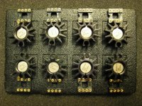
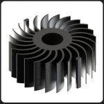
Yes the BUF03 runs very hi bias, it needs a big heatsinks, I use one like the one in the first pic but they still hit 50c, (no oscillations). The one in the second pic would be nice.
I believe the sweetness of the highs and rich midrange comes from the amount of class A bias, but the punch and awesome bass tightness, comes from the 1ohm output impedance and peak 100mA output current.
Cheers George
Attachments
does it still have heavy switch on and off dc swings for a couple of seconds?
Cheers George
I've not measure that.
Tim
I will let somebody post first - yes I used the 844 with TDA1541A - so this is de ja vu for me. So when I see a post/schematic, I will chime in with my two-cents worth.
Cheers, joe
.
Well, I didn't figure it out. I was actually searching for where to buy BUF03 and found from 21st September 2013, 08:47 PM:
--------------------------------
Quote ON
Stacking avert techniques
Hi Guys
I promised George to post this last time we met up on August the 1st, and of course we discussed matters related to AD844's.
I said I would show a couple of techniques that overcomes the need for stacking.
I am not saying not to stack, but simply that the reason for stacking is that in the OTA part (Diamond Transistor) current is so low, almost certainly sub 1mA. Hence, what other shots do we have in our armory? Worth at least looking at.
George feels the input impedance, what is seen by the DAC, is also important to keep low, and indeed the ideal has always be zero Z. But does 0 to 50 Ohm make that much of a difference? I see many using TDA1541A into 33R and then tubes afterward (a la Steve Garland's KillerDAC). They don't complain about the sound. How much does the DAC deteriorate not seeing zero Z? It's a matter of degree. Relative to the high Z of the DAC, it can be argued minimally.
Hera two techniques shown here will reduce the DAC's current to overwhelm that of the OTA part of AD844:
Technique 1.

Zero current induced into the OTA.
The 39R here replicates what is normally seen on "-" input in Pedja's original circuit, which I saw first time about ten years ago.
Now, with this arrangement, then all DAC's current goes to ground via 39R, as "+" input is high Z.
The component values shown are only guides and the caps are filters and may/will vary from DAC to DAC (use one or the other or both, but get their values right as they do affect the sonics). The 1K8 value is adjusted to gives 2.0V RMS output. Any DC offset can be trimmed used by the facility inbuilt in the buffer, by simply adding a 20K trimpot from Pin 1 and Pin 8 and the wiper to Pin 7.
Note, as George told me he does, the output can be taken from Pin 5 (by-pass internal buffer) and then use a separate buffer like BUF03 etc.
Technique 2.

This one may interest George as it actually makes the DAC see a much lower Z than even stacking could achieve.
The nominal input Z on "-" is 50 Ohm (that may be a max spec or more like 40?). But using a much lower value (about 1/10th) the current gets shunted to ground and very little DAC current ends up upsetting the OTA.
This may well be an equivalent of stacking up to 10 x AD844?
All the other details as far as constructing this, is the same as for Technique 1. That 18K value shown indicates that much higher gain is required, but the AD844 is suitably low noise and can handle it, so adjust 18K to give 2.0V RMS output.
Quote OFF
---------------------
From:
http://www.diyaudio.com/forums/digital-source/227677-using-ad844-i-v-62.html#post3640844
Last edited:
My bad I keep thinking you are using the AD844 TZ pin, still I wonder what that output impedance is (Terry you got an idea),
Cheers George
OP Z of what George, I have not really followed this thread.
PS where did you get your BUF03's?
TZ
And then:
from:
http://www.diyaudio.com/forums/digital-source/227677-using-ad844-i-v-63.html#post3641799
...
So about 3.6mA (must tie Pin 1 to 4 via 10R) and that means that clearly the 844 is measured uA.
But look at my Technique 2. in Post #615, that would be my preferred option in any case, whether with either 844/680/681 because I know it works. I have done it many times with both 860 and 844. With 844 that 4R7 is way lower that "-" input Z and in the case of 680/681 still lower than 10 Ohm, but current headroom much better than 844. So all bases are covered with that technique.
It's not theory, it works!
...
Cheers, Joe
from:
http://www.diyaudio.com/forums/digital-source/227677-using-ad844-i-v-63.html#post3641799
Good, because the 844 does for a .5sec off/on about 100mV dc offset, I had to utilize the players mute circuit which grounds the output for a couple of seconds on switch on and off, but the BUF03 can take it.
I'd rather have switch on/off thumps than have any cap in the signal path, no matter how esoteric it is.
My system is now dc coupled from the PCM1704's outputs all the way to the speakers, not one cap in the signal path.
Cheers George
I'd rather have switch on/off thumps than have any cap in the signal path, no matter how esoteric it is.
My system is now dc coupled from the PCM1704's outputs all the way to the speakers, not one cap in the signal path.
Cheers George
Opamp output stages tend to suck because they're class B. In other words, if you don't like the sound its most likely due to power supply noise, not the opamp itself. Bias it up with a CCS and see how the sound improves. Add more caps to the rails, ditto. Optimum is running differential with two CCS but even then more caps sounds better.
Increased punchiness is a classic attribute of class A (i.e. lower PSU noise).
Very interesting. Do you guys think a class A bias with a single or cascoded jfets would be worthwile in 2 or 3 stack AD844? Are there any drawbacks?
Biasing Op-Amps into Class A
That article takes the traditional view of class A - that its about reducing crossover distortion (and thermal distortions). I don't subscribe to that view, but that by no means negates their circuit proposals.
Drawbacks of class A biassing are increased circuit complexity and increased power consumption. Both a small price to pay for improved punchiness (aka dynamics).
Drawbacks of class A biassing are increased circuit complexity and increased power consumption. Both a small price to pay for improved punchiness (aka dynamics).
... but that by no means negates their circuit proposals.
Drawbacks of class A biassing are increased circuit complexity and increased power consumption. Both a small price to pay for improved punchiness (aka dynamics).
Which circuit would you recommend (hmm, simple vs complex
 ) and why? Other?


And to quote their Resources section:
Other Resources
For another explanation of these issues, which may help your understanding, see the following post on Audio Asylum:
Re: Op Amps running Class A? - Jon Risch - Tweakers' Asylum — by Jon Risch
For an alternate explanation of the action of the JFET cascode, see section 3.06 in The Art of Electronics: Paul Horowitz, Winfield Hill: 9780521370950: Amazon.com: Books 2/e.
Yet another explanation of the cascode is in Siliconix application note AN103 http://www.vishay.com/docs/70596/70596.pdf, "The FET Constant-Current Source/Limiter". Of particular value in this document is that it gives equations for determining the proper Rs value given the desired current level and the IDSS value of the Q1 JFET you’re using.
Well, I didn't figure it out. I was actually searching for where to buy BUF03 and found from 21st September 2013, 08:47 PM:
--------------------------------
Quote ON
Stacking avert techniques
Hi Guys
I promised George to post this last time we met up on August the 1st, and of course we discussed matters related to AD844's.
I said I would show a couple of techniques that overcomes the need for stacking.
I am not saying not to stack, but simply that the reason for stacking is that in the OTA part (Diamond Transistor) current is so low, almost certainly sub 1mA. Hence, what other shots do we have in our armory? Worth at least looking at.
George feels the input impedance, what is seen by the DAC, is also important to keep low, and indeed the ideal has always be zero Z. But does 0 to 50 Ohm make that much of a difference? I see many using TDA1541A into 33R and then tubes afterward (a la Steve Garland's KillerDAC). They don't complain about the sound. How much does the DAC deteriorate not seeing zero Z? It's a matter of degree. Relative to the high Z of the DAC, it can be argued minimally.
Hera two techniques shown here will reduce the DAC's current to overwhelm that of the OTA part of AD844:
Technique 1.
View attachment 413403
Zero current induced into the OTA.
The 39R here replicates what is normally seen on "-" input in Pedja's original circuit, which I saw first time about ten years ago.
Now, with this arrangement, then all DAC's current goes to ground via 39R, as "+" input is high Z.
The component values shown are only guides and the caps are filters and may/will vary from DAC to DAC (use one or the other or both, but get their values right as they do affect the sonics). The 1K8 value is adjusted to gives 2.0V RMS output. Any DC offset can be trimmed used by the facility inbuilt in the buffer, by simply adding a 20K trimpot from Pin 1 and Pin 8 and the wiper to Pin 7.
Note, as George told me he does, the output can be taken from Pin 5 (by-pass internal buffer) and then use a separate buffer like BUF03 etc.
Technique 2.
View attachment 413402
This one may interest George as it actually makes the DAC see a much lower Z than even stacking could achieve.
The nominal input Z on "-" is 50 Ohm (that may be a max spec or more like 40?). But using a much lower value (about 1/10th) the current gets shunted to ground and very little DAC current ends up upsetting the OTA.
This may well be an equivalent of stacking up to 10 x AD844?
All the other details as far as constructing this, is the same as for Technique 1. That 18K value shown indicates that much higher gain is required, but the AD844 is suitably low noise and can handle it, so adjust 18K to give 2.0V RMS output.
Quote OFF
---------------------
From:
http://www.diyaudio.com/forums/digital-source/227677-using-ad844-i-v-62.html#post3640844
Correct me if I'm wrong and not seeing it right here, but isn't there a noise penalty to pay doing these, don't these circuits both drop the level of the dac externally (unlike the 844 the way we've used it), just so one has to amplify much more again down the line to get get it back up "along with the increased noise"? And why is pin 6 taken to ground?
Cheers George
OP Z of what George, I have not really followed this thread.
PS where did you get your BUF03's?
TZ
eBay Asia. (but be carefull there maybe fakes in amoungst them) Try to get the "AJ" they are better spec'd and are lower in dc offset, so sometimes you don't have to use the nulling pin circuit.
Cheers George
- Home
- Source & Line
- Digital Line Level
- Using the AD844 as an I/V