I've also tried the stacked 844's and can hear why George was so impressed-I've never heard a TDA1541 sound like this, and I've owned and built more than a few. I used 3 stacked 844's but ordered more as probably need to put another one on to suit the 1541.
As George says it is very dynamic, very defined, none of the "euphonic" sound commonly found with 1541's. I'm using Pedja Rojics 2SK170 buffer, but I suspect the 844 will work with any buffer. It certainly brings out the very best from a 1541 and should make a significant difference to all R2R dac chips.
I'm not really a 16 bit dac guy but I'm really enjoying this dac- its like having an old girlfriend turn into a super model!
Nice work George.
Thanks Supra, glad to see someone has given it a go and found the magic that happens when stacking.
I believe that even with the PCM1704's 1.2mA output a single AD844 maybe current starved, maybe not by the signal transients but by the very hf glitches these have and these could be causing the problem of current starvation when a single is used. Or it's the halving of the input impedance when stacking.
Oh I also have another 2 must do's, I think maybe the TZ output does not like to see capacitive loading, all I have now is a TZ resistor of 4.7kohm between it and the buffer fets, even the input of whatever buffer you are using remove any filter caps to ground, so TZ doesn't see it. I measured the noise on the output, and has gone up slightly to 2mV but in the 10's of megahertz region, definitely can't hear it, and all dc offsets are still .1mV stable, after initial switch on and off spikes, I really have to get around to muting that as it will when I'm not careful one day take out my amps.
Also if the buffer you are using can handle it make the input impedance at least more than 1meg ohm, as I have done some tests on the bench and the TZ output drops by around 10% when it see's a 100kohm load, so now I have nothing between the TZ and fet inputs of the buffer except for the TZ resistor itself, and all is stable and wickedly fast.
Cheers George
Last edited:
I don't really care if it "sounds" good to anyone, but paralleling opamps is not easy, and stacking them is definitely not recommended, according to TI:
Paralleling Op Amps?is it possible? - The Signal - Blogs - TI E2E Community
Paralleling Op Amps?is it possible? - The Signal - Blogs - TI E2E Community
TI only say this when there is global feedback around it, I could imagine there is maybe a problem this way, they don't say anything running it with no feedback as we are. As well we are only stacking the input i/v and not the buffer section. You need to hear the difference to make up your mind with an absolute to if it works or not.
Cheers George
Cheers George
AD844
Hi, I have tried the AD844. Liked it for a while. That was using Pedja's original Aya II schematic. I have had better luck with the Discrete DDNF circuit that Pedja posted some years ago. It sounds just as has been described here. There is a lot more current through the mirrors on that one. It sounds like 4 stacked 844's is the optimum for 1541's? I may have to try reworking my 844 board to use the TZ output and a buffer. That was something I never tried. Would be interesting to compare those.") Based on a comment seen here I tried the OPA627 as an I/V. In my DAC that was real nice. I have simple I/V (no Sallen Key filter crap), GIC Bessel 7th order filter and AD8065 buffer. Awesome bass, clean with great drive.
Based on a comment seen here I tried the OPA627 as an I/V. In my DAC that was real nice. I have simple I/V (no Sallen Key filter crap), GIC Bessel 7th order filter and AD8065 buffer. Awesome bass, clean with great drive. 
Hi, I have tried the AD844. Liked it for a while. That was using Pedja's original Aya II schematic. I have had better luck with the Discrete DDNF circuit that Pedja posted some years ago. It sounds just as has been described here. There is a lot more current through the mirrors on that one. It sounds like 4 stacked 844's is the optimum for 1541's? I may have to try reworking my 844 board to use the TZ output and a buffer. That was something I never tried. Would be interesting to compare those.
Based on a comment seen here I tried the OPA627 as an I/V. In my DAC that was real nice. I have simple I/V (no Sallen Key filter crap), GIC Bessel 7th order filter and AD8065 buffer. Awesome bass, clean with great drive. If you liked the OPA627 as an I/V, your in for a shock (dynamically) with the stacked AD844's and the signal taken from TZ to a good dc coupled solid state buffer. Just make sure the buffer is at least 1megohm input impedance, as I found that the TZ output droped by 10% when loaded down with 100kohm.
Also try to remove any capacitance that the TZ point may see, so long as you do not end up getting any audible noise in the end, as I have a suspicion that the TZ output prefers to see nothing on it's output, just the TZ resistor and the input of the fet buffer.
Cheers George
Also try to remove any capacitance that the TZ point may see, so long as you do not end up getting any audible noise in the end, as I have a suspicion that the TZ output prefers to see nothing on it's output, just the TZ resistor and the input of the fet buffer.
Cheers George
844's
Hi George, Sounds like a BUF03 might be good as a buffer for the TZ output pin. FET input very high input impedance. I have several of those. Never cared for the sound of the BUF04 or AD811's. Have you tried Pedja's discrete current mirrors? I see the PDF was posted earlier in this thread. I may try the OPA637 for I/V, if they are affordable. I think these maybe very expensive now. If you know of a better buffer please point me to it. Dave
Hi George, Sounds like a BUF03 might be good as a buffer for the TZ output pin. FET input very high input impedance. I have several of those. Never cared for the sound of the BUF04 or AD811's. Have you tried Pedja's discrete current mirrors? I see the PDF was posted earlier in this thread. I may try the OPA637 for I/V, if they are affordable. I think these maybe very expensive now. If you know of a better buffer please point me to it.
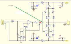
DaveVery happy with the buffer I'm using at the moment http://www.diyaudio.com/forums/atta...ng-ad844-i-v-fetbuffer-2-dc-offset-adjust.jpg
But I have found this ready made one on ebay, do you buffer gurus think it's any better than the one I'm using? As the one I'm using I have measured at 100ohms output impedance, I would like to get lower if possible if this is or it's a better circuit?
Cheers George
But I have found this ready made one on ebay, do you buffer gurus think it's any better than the one I'm using? As the one I'm using I have measured at 100ohms output impedance, I would like to get lower if possible if this is or it's a better circuit?
Cheers George
Attachments
Hey George, sorry I dropped off the face of the earth but I see you've been going great guns! You are a wild man: no fear, I love it!
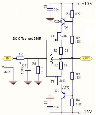
Looking into the output of your buffer, the lowest resistance is the pairs of 22 ohms on the top and bottom. So that means you'd see four 22 ohms in parallel or 5.5ohms.
Layout will be important, care to share the address or is it hush-hush ...
The output is doubled and the other trans must be doing some sort of cascode-thingy that I'll let the smart people talk about.
It's hard to find the BUF03 chip buffer but the BUF634 and LT1010 are plentiful.
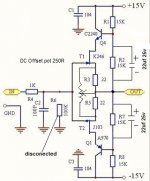
Torchwood, would you mind sharing details of your 1541 offset adjust circuit and what the process is for connecting it the first time (paranoid about hurting my 1541s). Thanks.
Cheers,
Jeff
Looking into the output of your buffer, the lowest resistance is the pairs of 22 ohms on the top and bottom. So that means you'd see four 22 ohms in parallel or 5.5ohms.
Layout will be important, care to share the address or is it hush-hush ...
The output is doubled and the other trans must be doing some sort of cascode-thingy that I'll let the smart people talk about.
It's hard to find the BUF03 chip buffer but the BUF634 and LT1010 are plentiful.
Torchwood, would you mind sharing details of your 1541 offset adjust circuit and what the process is for connecting it the first time (paranoid about hurting my 1541s). Thanks.
Cheers,
Jeff
Last edited:
George - I can't remember if this has been discussed before but what are you using to power your AD844s? Hopefully not zeners like in that schematic - low impedance supplies are a must I've discovered. I have some simple shunts on my blog which you could try - they sound even better when lots of uF is added to them. Also what supplies are feeding your PCM1704s? My TDA1387s took a step up when I lowered their supply impedance.
Hey George, sorry I dropped off the face of the earth but I see you've been going great guns! You are a wild man: no fear, I love it!
Looking into the output of your buffer, the lowest resistance is the pairs of 22 ohms on the top and bottom. So that means you'd see four 22 ohms in parallel or 5.5ohms.
Layout will be important, care to share the address or is it hush-hush ...
The output is doubled and the other trans must be doing some sort of cascode-thingy that I'll let the smart people talk about.
It's hard to find the BUF03 chip buffer but the BUF634 and LT1010 are plentiful.
Torchwood, would you mind sharing details of your 1541 offset adjust circuit and what the process is for connecting it the first time (paranoid about hurting my 1541s). Thanks.
Cheers,
Jeff
This is the one I'm using now, and when I loaded it's output with 100ohm I got half the output, so it's output is 100ohm a bit high for a discrete I thought.
Cheers George
Attachments
My AD844's are powered from whatever powered the original opamp opa627 I/V in the Cary CDP, I'm using the same socket.
I suggest fitting some aftermarket shunt regs then - on my blog there are simple and compact ones which manage around 10mohm output impedance at low frequencies. Adding low impedance electrolytics extends the low impedance to beyond the audio band.
...
I'm with Dirkwood that stacking is definitely getting into voodoo territory. My eyes start to cross as I try to follow the currents around one 844 circuit and its PCB layout; putting 3 on top of each other = Scanners type head explosion! Especially with high speed chips!!11! If you wanted to do this, SM would be best to minimize parasitics and interactions. I so wish you had a scope and could check for rock-solid hi freq. stability and minimal ringing...
But given that many have commented on the lack of large currents inside the chip, I think this is crying out for a discrete copy circuit using ultra matched trans. from some other chip/part. Give 'em your requirements (LightSpeed 7k input) and let 'er rip!
I'm with abraxalito, get some good power supplies on that buffer. You could start with some extra on-board bypass (me: Pan FM 68uf, 35V) [Or you could remove the small caps and put the electros on top, small caps on bottom sideways and tight.]
Last edited:
All I know is 2 kills one, maybe it's the halving of the input impedance, or the glitches are not creating any current starvation. I'm also only stacking the I/V stage not the buffer. The sound is so much better with 2 stacked.
Mick Meloney (Supratek) has found the same when he stacked 3 for the TDA1541
http://www.diyaudio.com/forums/digital-source/227677-using-ad844-i-v-35.html#post3476672
So impressed was he he is going for 4 or 5 because of the higher output from the TDA1541 4mA.
As for the power supply for the buffer it is using a well regulated one that powered the opamps that Cary had in there.
Abraxilito have you a link to your shunt regs as i cannot find them.
Cheers George
Last edited:
I can't argue with your ears and am merely providing a hopefully appropriate mid level description of potential issues. Oscillations, intermittent oscillations, ringing, power supply modulation, hf instability, etc can all sound 'different' and has ... er, .... sigh ... fooled me in the past.
I am humble before my ears and shoot for technical stability and full operation before subjective judgement. But I cannot because I am an impatient DIYer with no scope.
You are bolder than I sir! Just go for it! ... but someday get a 'scope on that thing!
Ah, there they are:


As for the power supply for the buffer it is using a well regulated one that powered the opamps that Cary had in there.
That may be true however as soon as those brown, green and blue wires leave the original PCB and travel even that short distance to the buffer they loose their HF bypass ability.
The same principles apply to the wide spacing of the V+, v- and GND pads on the buffer PCB. Even if we followed the general good advice of twisting a GND wire with each power-supply wire from the original PCB up to the buffer, we'd lose some of the twisting's effectiveness as we hit the wide spacing on the buffer PCB.
So we want good hf and low freq power-supply bypassing on the buffer PCB (small hf cap and big electro.)
It also looks like you have an older version of the buffer compared to mine: I'm not sure about the hf caps on your board. Perhaps others could offer good technical part recommendations for both caps.
I would love to see if you hear a difference.
Hmmm
View attachment G's opamp bypass.bmp
Interesting asymmetry in the ps bypass. Top of chips: hf and electro as close as possible--nice. Bottom: hf and electro a bit further behind a filter or something. If you can get at the back side of the PCB you could try removing the two caps and soldering them right to the pins of the opamp socket (top set too since on the pins is pretty much 'as close as possible') BUT you need appropriate GND connections super close ... we'd have to see.
Keep going you madman!
Cheers,
Jeff
I am humble before my ears and shoot for technical stability and full operation before subjective judgement. But I cannot because I am an impatient DIYer with no scope.
You are bolder than I sir! Just go for it! ... but someday get a 'scope on that thing!
Ah, there they are:
As for the power supply for the buffer it is using a well regulated one that powered the opamps that Cary had in there.
That may be true however as soon as those brown, green and blue wires leave the original PCB and travel even that short distance to the buffer they loose their HF bypass ability.
The same principles apply to the wide spacing of the V+, v- and GND pads on the buffer PCB. Even if we followed the general good advice of twisting a GND wire with each power-supply wire from the original PCB up to the buffer, we'd lose some of the twisting's effectiveness as we hit the wide spacing on the buffer PCB.
So we want good hf and low freq power-supply bypassing on the buffer PCB (small hf cap and big electro.)
It also looks like you have an older version of the buffer compared to mine: I'm not sure about the hf caps on your board. Perhaps others could offer good technical part recommendations for both caps.
I would love to see if you hear a difference.
Hmmm
View attachment G's opamp bypass.bmp
Interesting asymmetry in the ps bypass. Top of chips: hf and electro as close as possible--nice. Bottom: hf and electro a bit further behind a filter or something. If you can get at the back side of the PCB you could try removing the two caps and soldering them right to the pins of the opamp socket (top set too since on the pins is pretty much 'as close as possible') BUT you need appropriate GND connections super close ... we'd have to see.
Keep going you madman!
Cheers,
Jeff
Last edited:
I have scoped it, with a 200meg Tek with all my tech bench test disc's till I was xeyed. Stable as rock under all conditions.
What happened sound wise with the 2x stacking was a sense of ease to everything, like there is now unlimited headroom for want of a better word. Yet the dynamics, punch and transparency and detail are still all there as it was with one.
I have all left off all fitering caps, across TZ resistor and the input of the buffer and no input resistor to the buffer, TZ straight into the fets. I do have 2mV of very high noise now on the output, but it's so high even the scopes 20mhz filter doesn't touch it, I scoped it all the way back to the PCM1704's itself giving it out, nothing to do with the AD844's or buffers.
Cheers George
Cheers George
My apologies, I assumed too much.
You are inspiring me to dig out my malfunctioning 844 PCB ...
Perhaps some of the more HF testing competent member will chime in on further specific test you could try. Or specific tests to try and nail down what factors are responsible for its good sound.
I look forward to your further developments!
Cheers,
Jeff
PS I was referring to the buffer ps hf caps.
Abraxilito have you a link to your shunt regs as i cannot find them.
http://www.diyaudio.com/forums/blogs/abraxalito/1004-force-sense-shunt.html
@ALD - I suspect the reason for the good sound is lower intermodulation distortion. Its a big challenge in I/V amps to get decent IMD performance, having feedback makes it even harder to get lower IMD. Check out Bruno Putzeys article on feedback which is available from Linear Audio - there he has a plot of feedback factor vs harmonic distortion. Then work out how much feedback is needed to get the same high order distortion performance (talking here 9th harmonic and above) at the top end of the audio band as against an open loop design.
Last edited:
These super HF super fast "glitches" that come out of dacs I read about, does anyone know frequency, amplitude, duration and how often they occure, or are these a bit of a mystery? Even though the PCM1704 data sheet says they are glitch free, apparently they are not.
Cheers George
Cheers George
- Home
- Source & Line
- Digital Line Level
- Using the AD844 as an I/V