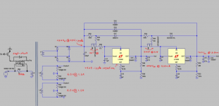
I need your advises in regarding how safe it is to mount a high voltage NMOS STW12NK95 directly the chassis for heat dissipation purposes.
The operating voltage of the power NMOS(M4,M3) is 420VDC. The chassis is obviously earthed. The power supply is designed to float e.g. isolated from earth, (but let assume the worst case scenario that it is not)
I know that an insulating/thermal pad can be insert between the NMOS and the aluminium chassis to achieved electrical isolation. But is this enough? Is this safe? Please do shared any documented works that shows how to do it safely.
Attachments
Last edited:
I know that an insulating/thermal pad can be insert between the NMOS and the aluminium chassis to achieved electrical isolation.
But is this enough? Is this safe?
The chassis is earthed, so the line fuse will blow should any short to chassis happen. A dedicated internal heat sink would work better, though.
https://www.infineon.com/dgdl/Infin...s.pdf?fileId=db3a30433d1d0bbe013d20e0cbf017fe
I need your advises in regarding how safe it is to mount a high voltage NMOS STW12NK95 directly the chassis for heat dissipation purposes.
The operating voltage of the power NMOS(M4,M3) is 420VDC. The chassis is obviously earthed. The power supply is designed to float e.g. isolated from earth, (but let assume the wost case scenario that it is not)
I know that an insulating/thermal pad can be insert between the NMOS and the aluminium chassis to achieved electrical isolation. But is this enough? Is this safe? Please do shared any documented works that shows how to do it safely.
The weak point safety-wise is the screw holding the MOSFET down, even with insulating shoulder washers. I have IRFP450 MOSFETs mounted to the chassis of my amps using an insulating "sock" over the part and pressure clips holding it down. When I get back to my PC I'll post the details.
The weak point safety-wise is the screw holding the MOSFET down, even with insulating shoulder washers.
Nylon screws and nuts just might be the answer to this issue.
Nylon screws and nuts just might be the answer to this issue.
The problem with nylon is it fatigues over repeated heating and cooling cycles, eventually leading to failure of the screw. PEEK screws might work, but they're hard to find and very expensive. In any case, with screws of any type there has to be a hole in the insulator for the screw to pass through. No screw, no hole, no weak point in the insulation.
Last edited:
You can use these insulators that slip over the part; depending on the package (TO-220, TO-247, etc.) they have different sizes:
THINC33-TO247-28.5-17.5-5.8-0.3 t-Global Technology | 1168-1957-ND | DigiKey
and these clips or similar to hold them down:
MAX07NG Aavid Thermalloy | Mouser
THINC33-TO247-28.5-17.5-5.8-0.3 t-Global Technology | 1168-1957-ND | DigiKey
and these clips or similar to hold them down:
MAX07NG Aavid Thermalloy | Mouser
The chassis is earthed, so the line fuse will blow should any short to chassis happen. A dedicated internal heat sink would work better, though.
https://www.infineon.com/dgdl/Infin...s.pdf?fileId=db3a30433d1d0bbe013d20e0cbf017fe
Thanks for the document.
The fuse indeed should blow. I just wanted to prevent it happened from improper mounting of the power NMOS, or when in the unlikely event where the earth wire failed.
The weak point safety-wise is the screw holding the MOSFET down, even with insulating shoulder washers. I have IRFP450 MOSFETs mounted to the chassis of my amps using an insulating "sock" over the part and pressure clips holding it down. When I get back to my PC I'll post the details.
You can use these insulators that slip over the part; depending on the package (TO-220, TO-247, etc.) they have different sizes:
THINC33-TO247-28.5-17.5-5.8-0.3 t-Global Technology | 1168-1957-ND | DigiKey
and these clips or similar to hold them down:
MAX07NG Aavid Thermalloy | Mouser
This thermal cover look like what I needed, unfortunately I won't have access to neither Digikey and Mouser (international delivery fees is $100). I will try to search around the local store. My other option is the traditional thermal sheet insulating pads.
Never mind, just found some from the local store https://au.rs-online.com/web/p/thermal-gap-pads/4980297/.
Magz, aside from slip the part into the thermal cover and used the clips to hold it down, do you need to apply any thermal grease? what is the MOSFET operating voltage and how many watts does it dissipate? Any problems so far?
pha001 you really should work out your worst-case power dissipation, as you know the circuit operation. You can then work through the thermal design equation for Tj, Tc, Ta by using some general assumptions. Perhaps have a go at describing the calculation for us with the values you use. Perhaps design for Tj under 110C, rather than the datasheet max.
Most pads don't need thermal grease - certainly if your design has enough safety margin. You could wrap some sheet around, as per a tube - not as neat, and not as failsafe if the clip loosens or solder debris floats about, but a quick workaround.
Most pads don't need thermal grease - certainly if your design has enough safety margin. You could wrap some sheet around, as per a tube - not as neat, and not as failsafe if the clip loosens or solder debris floats about, but a quick workaround.
Last edited:
Never mind, just found some from the local store https://au.rs-online.com/web/p/thermal-gap-pads/4980297/.
Magz, aside from slip the part into the thermal cover and used the clips to hold it down, do you need to apply any thermal grease? what is the MOSFET operating voltage and how many watts does it dissipate? Any problems so far?
No grease needed, in fact it will make thermal performance worse. I use the socks and clips because I float the MOSFET at 250VDC, so the tab is elevated with respect to the chassis. It's a bit of extra protection.
Nylon screws and nuts just might be the answer to this issue.
Not on a device burning a lot of power.
Not on a device burning a lot of power.
3W aint a lot of power!
Nylon shoulder washers suck! I only use Polyphenylene Sulfide (PPS) washers. See here:
7721-7PPSG Aavid Thermalloy | HS418-ND | DigiKey
7721-7PPSG Aavid Thermalloy | HS418-ND | DigiKey
Never mind, just found some from the local store https://au.rs-online.com/web/p/thermal-gap-pads/4980297/.
Magz, aside from slip the part into the thermal cover and used the clips to hold it down, do you need to apply any thermal grease? what is the MOSFET operating voltage and how many watts does it dissipate? Any problems so far?
Missed the last part of your question. The IRFP450 is dissipating 44W and I haven't had any issue in about 1.5 years.
Magz, you must have a very good heatsink and interface!
Perhaps you can walk us through the thermal design of getting 44W out of a T03P junction and in to ambient for an amp. I doubt amp makers would have that capability and still leave some margin for safety.
It's dropping 250V at 175mA, or 44W. The TO-247 IRFP is good for 190W at 25C; of course that needs to be derated as the temp goes up.
The MOSFET is attached to the center of the side of a 22"x18"x4.25"x3mm aluminum chassis, with an additional 11"x4" heat sink bolted to the side panel, fins oriented vertically. The chassis contains a Noctua low noise fan sucking cool air from beneath the amp and blowing it out up around the 833C tube, in the process keeping a stream of cool air flowing through the chassis. Based on measurements of the heat sink at its hottest point and back calculating the junction temp using the thermal impedances between the chip and the sink, I came up with about 108C, which would derate the power handling to about 65W under these conditions.
Not a huge margin but a margin nonetheless. 1.5 years of operation to date and no meltdown of the MOSFET.
One more thing. The MOSFET in question is in the cathode of the 833C as part of a shunt voltage regulator supplying the cathode bias voltage, and is sinking all of the 833C current plus 15mA of regulator standing current. Interestingly, the big milliammeter on the front panel of the amp is in effect a thermometer for the MOSFET temp - as the MOSFET heats up the bias voltage supplied to the cathode drifts down slightly, and thus the 833C current increases. If I measure the heat sink temp and watch the milliammeter they both change at the same rate until the MOSFET hits thermal equilibrium, then they both stop moving.
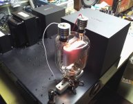
In the attached pic you can see the heat sink; after this pic I added another one of the same size behind it on the side panel as the temp was getting a bit too high. Now it stays in the range of 53-57C at the hottest part of the heat sink (dependent on room temp).
It's an interesting inter-dependence at work - the fan draws cool air in the bottom back of the chassis, which pulls heat from the internal components and the chassis, cooling them and warming the air; that warm air is just what the 833C needs for cooling since if the air is too cool it can negatively affect the 833 operation, as it was designed to run hot. So far it all seems to work as designed (amazingly!).
Attachments
Last edited:
- Status
- This old topic is closed. If you want to reopen this topic, contact a moderator using the "Report Post" button.
- Home
- Amplifiers
- Tubes / Valves
- Use the chassis as the heatsink - Need safety advise