It's dropping 250V at 175mA, or 44W.
Based on measurements of the heat sink at its hottest point and back calculating the junction temp using the thermal impedances between the chip and the sink, I came up with about 108C
Nice setup Magz,
Rjc~0.65 C/W
Rc-hs ~ 1 to 1.5 for TO3P is at the top performance end depending on material and pressure.
Your ambient by the looks is unlikely to get much above 40C, but say it is 20C.
Your heatsink/chassis sounds like its performing at about (108-73-20)/44 = 0.31 C/W, which could be reasonable if the heatsink/chassis is receiving noticeable airflow.
Many amps would find it difficult to include such extensive heatsinking, or to keep heatsink/chassis in such a low ambient temp environment, or to ensure the pad is at the premium end of thermal conductivity scale.
pha001 you really should work out your worst-case power dissipation, as you know the circuit operation. You can then work through the thermal design equation for Tj, Tc, Ta by using some general assumptions. Perhaps have a go at describing the calculation for us with the values you use. Perhaps design for Tj under 110C, rather than the datasheet max.
Most pads don't need thermal grease - certainly if your design has enough safety margin. You could wrap some sheet around, as per a tube - not as neat, and not as failsafe if the clip loosens or solder debris floats about, but a quick workaround.
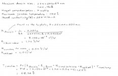
My thermal analysis skill is a bit rusty as this will be my first time doing it. But here are the calculations.
For my design, the MOSFET will dissipate 7 Watts(3Watts per channel). I worked out that the maximum junction temperature will be 68.9C. Does this seemed correct to you. The thermal resistance for the aluminium chassis seemed too good to be true... My assumption is 4C/W (chassis to air)
Attachments
Last edited:
Good try. Yes the chassis is your Achilles heel at only 1mm thick. You may be able to find some assessments of Rhs-a for 1mm alu, but you need to check if any such examples are the same as yours - eg. free air cooling on one side only(?); TO-220 point source of heat; vertical of horizontal plane of chassis.
If you can justify 25C max ambient, then for a 110C Tj, the heatsink performance needs to keep temp rise under 110C - 25C - 7W x 3C/W ~ 65C/7W. So heatsink must perform at <= 10C/W for a single T0220.
For such a thin chassis, it would be practical to use a spreader plate.
If you can justify 25C max ambient, then for a 110C Tj, the heatsink performance needs to keep temp rise under 110C - 25C - 7W x 3C/W ~ 65C/7W. So heatsink must perform at <= 10C/W for a single T0220.
For such a thin chassis, it would be practical to use a spreader plate.
Many amps would find it difficult to include such extensive heatsinking, or to keep heatsink/chassis in such a low ambient temp environment, or to ensure the pad is at the premium end of thermal conductivity scale.
One big advantage the hobbyist has over the commercial manufacturer - we can design our own amps knowing the actual conditions under which they will be used, in this case an air conditioned family room in a temperate climate. During the winter I turn the heat off when the amps are on; they make excellent forced-air heaters!
- Status
- This old topic is closed. If you want to reopen this topic, contact a moderator using the "Report Post" button.