Hi there,
1. I want to report that until now, DSD has worked with JRiver 18 (you have to enable DoP in the settings). I verified the DSD ON pin in the amanero board. Before, Jriver was converting to PCM but it sounded distorted, especially in program peaks or when raising DAC's internals volume. I think it's due to the fact that the DAC wasn't design to work with PCM at such a high sample rate (i am guessing here).
2. Now that DSD is working, I have been able to notice how suceptible is the cable conexion in between the Amanero board and the DAC board. I experiment different kind of hissings or noises that I was able to remove adding more Ground return cables between Amanero and DAC.
Noises are very subtle, and dont act as a Toslink unlock where music just stops for a bit. That makes me wonder , how much can I clean the sound?
I am wondering also how to improve connection even more (Buffalo III and Amanero).
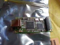
I did a small adapter PCB to conveniently replace the cs8412 in my dac with the amanero for experimental purposes.
The unmounted positions are for a LTC6655.
Thats a very good idea Tazzz!
In my case, Buffalo III and Amanero, I will try do to something similar but with this type of IDE connectors (don't know the name).
My idea is to reduce signal path distance and to have a closer Ground return for every signal.
Cheers,
Soooooo have we reached the number for the gb to start??
See post #1027
")
nice choice of reference, you are making a flea type buffered ref/reg?
not sure if youve used this part before? it really likes a larger cap for the filter/bypass for lowest noise. I use film
It's just the simple datasheet application example with an emitter follower circuit for boosted output current.
I´m going to use a 22uF polymer capacitor (+ all the on-board ceramics), looking at the block diagram it should be possible to use gain phase analyzer to see if something more/else is needed to avoid noise peaking and poor step load response.
Yes and mine has already shipped. He's fast...Soooooo have we reached the number for the gb to start??
Thats a very good idea Tazzz!
In my case, Buffalo III and Amanero, I will try do to something similar but with this type of IDE connectors (don't know the name).
My idea is to reduce signal path distance and to have a closer Ground return for every signal.
Cheers,
if you are making a PCB and the distance isnt too large. if you cannot use u.fl connectors you can try FFC/FPChttp://www.digikey.com/product-detail/en/SFV20R-1STE1HLF/609-4316-1-ND/2626767 connectors and cables like those used in phones and also on the fifo
It's just the simple datasheet application example with an emitter follower circuit for boosted output current.
I´m going to use a 22uF polymer capacitor (+ all the on-board ceramics), looking at the block diagram it should be possible to use gain phase analyzer to see if something more/else is needed to avoid noise peaking and poor step load response.
I dont necessarily mean size, but rather material. film just works out to be lower noise in this application, however the size needed does tend to dominate the layout so it needs to be kind of straddling over the rest of the circuit to keep as compact as possible.
If I were driving just a singular oscillator I would probably use something like wima MKS2 XL but since I do not want to cut up the amanero board Im going to have all those ceramics on there anyway so I think a polymer cap will be good enough.
Besides the application note does not mention polymer caps, do you or anybody else have further information with regard to their noise characteristics?
Besides the application note does not mention polymer caps, do you or anybody else have further information with regard to their noise characteristics?
if you are making a PCB and the distance isnt too large. if you cannot use u.fl connectors you can try FFC/FPCconnectors and cables like those used in phones and also on the fifo
The Bufalo and Amanero already have those connectores in place.
I also have limited space for the Amanero board in my enclosure.
So the plan is to build an as small as possible PCB for the routing, with two female connectors, so the Amanero will rest just above the Buffalo DAC.
mechanically, it will rest just on the connectors.
I think 40 pins for bufallo and 20 pins for Amanero.
no they dont, they have molex type 2.54mm pin connectors, one is designed for high speed data and has some impedance control measures, the other is used for easy availability/accessibility to hobbiests.The Bufalo and Amanero already have those connectores in place.
ZIF/FFC/FPC uses what is effectively a flexible thin stripline PCB as a cable
Last edited:
no they dont, they have molex type 2.54mm pin connectors, one is designed for high speed data and has some impedance control measures, the other is used for easy availability/accessibility to hobbiests.
ZIF/FFC/FPC uses what is effectively a flexible thin stripline PCB as a cable
Hi qusp,
Thanks for clarify that.
Yes, Amanero have 2.54mm connectores (the type you use to find in older computers).
Since I have those connectors in both boards, and given thatn i2c connections plus a ground return for each signal is not a 1 to 1 setup using a ribbon cable (sorry the terms, i usualy speak spanish) : I still need a PCB (or something like that to route connections.
Objectives, in my understanding is to get the shortest connections and to have independent GND returns for each signal.
That's why I am thinking a small PBC with two Molex 2.54mm connectors will be the best way to do the job.
I am not mounting the amanero on the Chasis, just will stack this PCB adaptor over Buffalo, and again will stack amanero over the adaptor.
Then distance should be minimal.
Would this be the best implementation? given Amanero an Buffalo already have Molex connectors?
Cheers,
Last edited:
hard to say, it depends on how well you route the traces on the board and how many times you will plug/unplug. probably your way will be fine, especially if you connect directly to the PCB (not with a cable or a socket, have you soldered the BIII sockets yet?) you could just use male pinheaders, which then solder directly into your adapter, but it would be semi-permanent
it depends, will you be using a lot of DSD and high rate PCM material?
it depends, will you be using a lot of DSD and high rate PCM material?
hard to say, it depends on how well you route the traces on the board and how many times you will plug/unplug. probably your way will be fine, especially if you connect directly to the PCB (not with a cable or a socket, have you soldered the BIII sockets yet?) you could just use male pinheaders, which then solder directly into your adapter, but it would be semi-permanent
it depends, will you be using a lot of DSD and high rate PCM material?
Yes, I expect that to be the only imput. I plan to stop using Coax Digital or Optical as I only use Music Servers as a source. This should be enough if I get the desired Sound Quality performance.

- Home
- Vendor's Bazaar
- USB to I2S 384Khz - DSD Converter