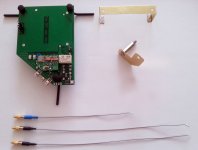
Battery powered clock.
216Mhz SAW oscillator parallel divided for DAC (108Mhz) and main processor (27Mhz). So, these components it get the same clock signal.
Alternative to this configuration, each oscillator for each component: 108Mhz SAW osc for DAC, and better quality oscillators for 27Mhz and 20Mhz.
The board provide access to each of the Enable pins of the 4 available oscillator footprints on-board. Mechanical mounting using vibrations damping system.
Attachments
Last edited:
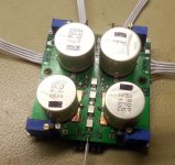
Balanced/unbalanced integrated module
It use OPA1632 and it include TPS adjustable regulators for +/- rails of I/V and for final buffers stages. Optional/customizable filter footprints are provided on the bottom side. 4 layer design. It fit well for the multichannel stage too, providing balanced outputs...
An upgraded version is already in production.
Attachments
I can confirm that using discovered here EPSON SAW oscillator 100MHz (I use XG-1000CB 100.0000M-CBL3) gives dramatic improvements, most of them are in extreme clarity of every produced sound especially in high frequency range. In fact, it is really big improvement.
In the same time I have to say that I didn't try other low jitter oscillator, for example Crystek 950 series so no direct comparisons.
So, things I did:
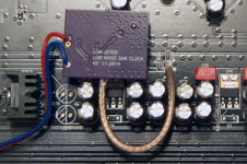
New oscillator for ES9018 with ultra low noise level line regulator ADM7150
LM4562 replaced by LME49720
some images
In the same time I have to say that I didn't try other low jitter oscillator, for example Crystek 950 series so no direct comparisons.
So, things I did:
New oscillator for ES9018 with ultra low noise level line regulator ADM7150
LM4562 replaced by LME49720
some images
Attachments
Good work! Nice to hear about confirmations...
Is this board your own design?
I have an observation about the insertion point for the new clock signal. As I can see. you injected the new clock exactly where it was the old oscillator. This is also one of the design issues of the 95 model: very long clock traces.
My suggestion is to inject the clock signal just at the DAC pin (and dismiss the rest of PSB trace), or very near to that. It may be better compromise to use two such clock modules for every DAC on board, but much closer to the target, than use a single oscillator for both DACs and with so huge length of the traces. However there is not good at all to transport 100Mhz on 10cm PCB traces. I will prefer more the coax instead...
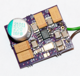
The ADM7150 is very easy in use so there were no any problems to design own PCB including production service (etching) 5$ (for 3 pieces 1 square inch high quality 2 layer PCB) free international shipping. Big tantals there in order to achive really ultra low noise at low frequencies according to ADM7150 datasheet.
Now I'm waiting for LME49720HA (metal can) (that version for the IC has sonic advantage over ordinary soic/dip versions) so I'll going to disassemble oppo again. Probably I'll try to inject Clock signal closer to ESS IC. Thank you for the advise.
Now I'm waiting for LME49720HA (metal can) (that version for the IC has sonic advantage over ordinary soic/dip versions) so I'll going to disassemble oppo again. Probably I'll try to inject Clock signal closer to ESS IC. Thank you for the advise.
Last edited:
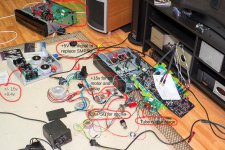
I think I've found my sweet spot.
Currently it looks like big mess") .
.
Anyways, there has been a debate on 105 forum about SMPS. I've tried to improve by better filtering original SMPS and to be honest I haven't noticed much of a difference.
The real treat started with fully regulated, discrete (no IC regulators), "ultra-low-noise" linear PSU by design of AMB Laboratories DIY Audio Site.
I must say, my OPPO 95 is in current state fully linear PSU driven, but the most significant improvement was getting rid of +5vSMPS and replacing it with above.
Since last post:
- (+)5v SMPS replaced with descrete, linear PSU (Very audible difference)
- tube output stage using only single phases of DAC stereo output - Burson opamps before
- capacitor between DAC output stages (love it!!!! 0.01uF)
- dedicated PSU for oscillators
- C&W oscillator for stereo and Crystek for M-ch, both 100Mhz - still cannot convince myself for SAW - just don't like it (forgive me!)
- better filtering of DAC analog and digital PS
I have no clue how am I going to box it. Tube stage is trouble some noise wise with close proximity of other electronics like oscillators PSU. SMPS replacement, linear PSU heat dissipation is quite a lot and enclosing it within player case would be difficult to implement.
My project practically makes no sense at all but it has been very educational and tons of fun! And it sounds DAMN GOOD!!!
Currently it looks like big mess
.Anyways, there has been a debate on 105 forum about SMPS. I've tried to improve by better filtering original SMPS and to be honest I haven't noticed much of a difference.
The real treat started with fully regulated, discrete (no IC regulators), "ultra-low-noise" linear PSU by design of AMB Laboratories DIY Audio Site.
I must say, my OPPO 95 is in current state fully linear PSU driven, but the most significant improvement was getting rid of +5vSMPS and replacing it with above.
Since last post:
- (+)5v SMPS replaced with descrete, linear PSU (Very audible difference)
- tube output stage using only single phases of DAC stereo output - Burson opamps before
- capacitor between DAC output stages (love it!!!! 0.01uF)
- dedicated PSU for oscillators
- C&W oscillator for stereo and Crystek for M-ch, both 100Mhz - still cannot convince myself for SAW - just don't like it (forgive me!)
- better filtering of DAC analog and digital PS
I have no clue how am I going to box it. Tube stage is trouble some noise wise with close proximity of other electronics like oscillators PSU. SMPS replacement, linear PSU heat dissipation is quite a lot and enclosing it within player case would be difficult to implement.
My project practically makes no sense at all but it has been very educational and tons of fun! And it sounds DAMN GOOD!!!
Attachments
That's insane Qkizz !!
WAF very low.... maybe even grounds for divorce.
well...she knew what she was getting into
Anyway, just recently I managed to render my +5V linear PSU useless and while waiting for some parts I was forced to plug back original SMPS.
It just fortified me even more in my opinion that it was the most significantly audible upgrade to my player.
well...she knew what she was getting into
Ahah! That's even more amazing, you are married?
.
Does anyone know which DAC implements the 4+4 stereo output on the Oppo BDP-95 to get better stereo output? Is it possible to tie the jumpers together on this DAC, and if so, which jumpers do you tie in?
Does anyone have pictures of doing this?
Thanks.
It is already done for you by Oppo on the stereo channels - in fact would be hard to separate them and you wouldn't want to do that anyway.
On the BDP-105 the situation is much more complicated and in fact 4+4 cannot be done because the logic circuit won't allow it (auto-senses headphones and no way to stop it from happening in the Settings).
So go for it.
Cheers, Joe
Thanks much Joe. I was under the impression on the BDP-95 that there are 4+4 Stereo Outs on the DAC that was not tied together. Its nice to hear that they did do this.
Only wish Oppo did the same with the '105 - the best you can do is 2+2 and you have to do it with jumpers.
- Home
- Source & Line
- Digital Source
- Upgrading & modding new Oppos, BDP-93 & BDP-95