Posted this in the 'saurus thread, but applies here too-
I think there are three threads going on Tiger related amps, but I'll toss this out here as it probably applies to all. My success with the Tiger amps may be closely related to being conservative with supply voltage. The devices don't have much safety margin, at least not the way I like to do things. It gets even scarier when you consider where in the SOA diagram the thing can end up operating with a reactive load. Throw in a high line voltage condition at the same time and all bets are off. Another amp that suffers from the same problem is the Marantz 250- I think I replaced every device in it. Designers like the Hfe and bandwidth of lower voltage devices and probably tend to go for overall performance rather than covering a worst case condition of high line voltage, Deep Purple and an excess of beer.
Lost my edit window while typing!
more thoughts:
SWTPCo also later recommended the TI 2N6331 and 2N6328 as output devices. I think those were made with a completely different process (it's been a while) than the Motorola MJ parts and it may have been done because there was a shortage of MJs. They worked OK but I always suspected they sounded a bit different. I don't know if sufficiently accurate models for the different devices exist that would reveal anything about amps built with the alternates. I can tell you it took just as much (or as little) effort and the same conditions to blow them up.
The basic Tiger is really a 0.03%+ THD amp, give or take, and rising with frequency. Higher bias will force it down a bit, but at the expense of very high power dissipation. It's very far from blameless and I can believe it has its own sound. I've built and rebuilt several, both factory kits and scratch built. In general they give lower THD with matched outputs, but it's nearly impossible to find complimentary devices that match. Having run out of matched devices I've also used highly mismatched devices and didn't have any unusual problems.
Last edited:
My success with the Tiger amps may be closely related to being conservative with supply voltage.
I think that is probably the reason that mine didn't blow up either.
a worst case condition of high line voltage, Deep Purple and an excess of beer.
In my case it was high line, high ambient temp, a blonde with a guitar, excess gain in the preamp, who knows what for a load (you can never have too many speakers in your stack) and an excess of multiple intoxicating substances. I did play Smoke On The Water, and there is only one proper volume setting for that song.
I made guitar amps using Plastic Tiger amps with TO-3 outputs (there was one board with to-3 sockets wired to it in the photo). There was a seperate amp board for each speaker jack. Plug in as many speakers as you want, if the house lights don't dim, the amp won't blow, but it WILL get hot!
Also, I consider the Tiger the first "Gainclone". When the article came out college students everywhere made boards and built copies. There must have been hundreds if not thousands built with no purchases from SWTPCo, plus a bunch purchased as kits. All this before the 'net.
Here in Rochester NY we had an office of Summit Electronics not far from Rochester Institute of Technology. There was a foot path over a small creek from the dorms to Summit. They had a will-call desk and you could order anything you wanted, then walk over and pick it up. Very often you could get the quantity price and there were no significant minimum orders. Pretty much any major brand semiconductor, or other part you needed, was just minutes away. Maybe its just the rose colored glasses of age, but I think DIY was easier and cheaper back then. Heck, when I built my Cordell distortion analyzer one of the local reps just sampled me an entire tube of NE/SE5534s to populate the boards, and it wasn't like I was any big time industrial buyer!
Here in Rochester NY we had an office of Summit Electronics not far from Rochester Institute of Technology. There was a foot path over a small creek from the dorms to Summit. They had a will-call desk and you could order anything you wanted, then walk over and pick it up. Very often you could get the quantity price and there were no significant minimum orders. Pretty much any major brand semiconductor, or other part you needed, was just minutes away. Maybe its just the rose colored glasses of age, but I think DIY was easier and cheaper back then. Heck, when I built my Cordell distortion analyzer one of the local reps just sampled me an entire tube of NE/SE5534s to populate the boards, and it wasn't like I was any big time industrial buyer!
I
Digging deeper in my folder, I found another mod to help reliability (adding 100pF to collector/base to q5-6, 47pf to q3, update r17,r18...) in 1973. Yikes! More bandaids.
rick
I think the original design should have had these miller compensation caps, with CFP output stage it's very easy to induce oscillations as I myself have found out in designing my own CFP output with a LME49810 input stage. If you have a look at Rod Elliots P3A , you will find some answers there also. Douglas Self's load invariant amp also follows a similar topology.An additional pair of output device might have helped, with a single pair they were exploring the limits of SOA of the devices.
I thought those miller caps would be a good idea too, but they destroyed the sound of the amplifier. I never bothered to find out exactly what the problem was- it wasn't simple response or some instability, maybe THD or a new spectral distribution of such, but it only took about 30 seconds of listening to say, "OMG, that was sure a mistake!"
What I was referring to above were strays. Unless you put in lead resistances and inductances, and probably even small capacitances to the chassis, the simulation doesn't reflect the real circuit. It certainly shows you where the weaknesses are, but I found that seemingly minor construction differences, where HF bypassing and the Zobel network were connected for example, made the difference between decent stability and constant oscillation. The value of the Zobel is also critical. The Tiger seems way more sensitive than other amps I've built, yet with the right construction it's reliable and doesn't oscillate. I assume it comes down to phase margin- make some unfortunate decisions in the physical construction and all bets are off. I built a very pretty one in a small rack chassis and it was junk. Nothing I did would cure the slight oscillation on musical peaks. I rebuilt it with the exact same components in a different physical configuration and it was stable as a stone.
Conrad, I am aware of the issues involving strays. I did SPICE sims of high speed digitial designs including package and trace transmission line effects many years ago on the job.
The simulation is showing global loop oscillations around 10 MHz under certain conditions and it seems that the lead cap is too large, have to take a closer look at the gain and phase margin. I did look at the stability far back in this thread, however I don't think that I had good device models at that time. I don't think the original Universal Tiger was ever "stable as a stone". The MKII version decreases the lead cap from 220 to 100 pF which is a step in the right direction.
Have you even run the SPICE model that I posted?
Hi Pete
I happen to have some MJ802/4502. Original Motorola (yr 1994). New-unused. 5 pairs in total.
If you like to have them, let me know.
Thanks for the transistors Michael, I have a friend who will make good use of them and I'll pass them on to him.
I mentioned a ways back in this thread my experiences years ago building these amps and also that I only had scratch built amps on hand at that time. I've kept an eye out on ebay over the years and have mentioned the design to a few friends which has led to:
Purchased 2 of the early stereo version of the Universal Tiger on ebay that were in really bad shape, one does not even have circuit boards. The other has burnt 100 ohm resistors and melted 1000 pF caps. I thought it would be good to use for a complete redesign for comparisons. These have Trout Audio Lab 1971 written on the inside and interestingly there is someone on DIYAudio that goes by Trout.
Also purchased 2 of the mono early version of the Universal Tiger on ebay that were claimed to be in perfect condition. They do look to be perfect, however whoever built them was very heavy on the solder. I am really tempted to redo all the solder lug joints and take a close look at the PC boards. They also look like they were stored in a damp basement with a mild layer of corrosion over them. I've not touched these since I don't want them to blow up and don't want to use them until the solder joints are cleaned up and mods to make them safe are put in. Have not even powered them up.
Someone gave my brother one mono MKII Universal Tiger - he has no use for just one so he gave it to us for analysis or whatever. I believe that this is the one that I will fix up stock, first as an original without the MKII changes to look for odd behavior. This one doesn't work and is an odd single unit so I don't mind using it for experimentation.
An old engineering colleague near by here in town mentioned that he built the Plastic Tiger and I mentioned that I was looking into the design so he gave me his box of parts. He had 2 original Plastic Tiger kits that were blown up. He said that his supply voltage was a bit high, and that when he first built them they would actually ignite in flames, LOL! He didn't know what was wrong at the time and just kept changing drivers and outputs until he probably lucked into a pair that would take the supply voltage, LOL! He also had 4 more hand etched Plastic Tiger circuit boards that are partially built up.
My only plan at this point is to get the single experimental unit going to take some measurements when I have some free time.
I've mentioned before that the 1000 pF polystyrene caps in the feedback path usually melt when a tiger blows up but I could not remember if they were very close to the resistors that also go up in smoke. Here is a picture of the circuit board in one of the amps that I purchased on ebay where it can be seen that the completely burnt resistors are not along side of the caps, no doubt the amp has stability issues:
Attachments
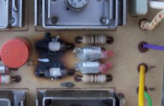
People forget that capacitors have to be de-rated for high frequency use.
I doubt that that cap can handle 10V above 10Khz (where it really needs to).
The Zobel cap is usually around 0.1µF in most designs. I always check this network after repair, I couldn't tell you how many times I have found this cap open.
I doubt that that cap can handle 10V above 10Khz (where it really needs to).
The Zobel cap is usually around 0.1µF in most designs. I always check this network after repair, I couldn't tell you how many times I have found this cap open.
I haven't read the whole thread, so I hope this comment isn't redundant.
The UT is an interesting design, but if you are talking about reliability and
stability, I have to chime it that it very likely would benefit from a little
degeneration on the input diff pair and an increase of output emitter
resistance to .22 ohms or so. It won't measure better, but it will probably
sound a little more relaxed...
Pete, I've always built them using silver-micas for those 1000 pF caps. It's hard to hurt a silver mica. FWIW, I did run the sim, but I'm more of a practical probe-in-hand kinda guy. It bothers me that none of the models are really the original devices and I don't know if they're close or not. They can't be too far off since the sim looks a lot like the real amp at audio frequencies, but is the sim valid at 10 MHz where it wants to oscillate? I do have a supply of all the original parts and can do about every measurement under the sun, from DC to daylight, but I don't know beans about how to convert those measurements to a good model.
I did something very similar to the UT back in the 90s. Rails were +/- 55Vc. Rated output was 200W/4 ohms. After ironing out the bugs, it was stable. Actually, I quite like the sound over the conventional EF outputs.
Information at: Schematic and Parts List
Feel free to use the component values. The amp could do with more modern transistors today. They were all I had then. I agree with Nelson, it would be better for the input differential to have some degeneration.
Information at: Schematic and Parts List
Feel free to use the component values. The amp could do with more modern transistors today. They were all I had then. I agree with Nelson, it would be better for the input differential to have some degeneration.
"relaxed" I like MTBF (stable). No burning amps. Before I moved on to triples , I tried the Szikai and had a complete workable amp that I cooked my load resistor with and did extended listening to (below 1). All modern fairchild/ON semi's and "blameless" level THD (powered by my "AX" voltage stage). C6 and especially 42 were essential to keep my zobel network from becoming slag This OP stage also required me to increase IPS degeneration to keep the same phase margin (simulated - below 2). It did , however , work as simulated (for 2 weeks in the barn).
OS
I like MTBF (stable). No burning amps. Before I moved on to triples , I tried the Szikai and had a complete workable amp that I cooked my load resistor with and did extended listening to (below 1). All modern fairchild/ON semi's and "blameless" level THD (powered by my "AX" voltage stage). C6 and especially 42 were essential to keep my zobel network from becoming slag This OP stage also required me to increase IPS degeneration to keep the same phase margin (simulated - below 2). It did , however , work as simulated (for 2 weeks in the barn).OS
Attachments
I've mentioned before that the 1000 pF polystyrene caps in the feedback path usually melt when a tiger blows up but I could not remember if they were very close to the resistors that also go up in smoke.
in my experience polystyrene caps are no good choice for use in vas and feedback............
they are heat - sensitive (melt down easily) and often they do not withstand more than 30vac.........
once i built a 50w amp with a 22pf polystyrene in the vas - the cap was destroyed and the amp failed.so i changed it to the 22pf ceramic -as shown in the original schematic- and everything worked fine.
polystyrene caps are no good choice for use in vas and feedback. heat - sensitive and often they do not withstand more than 30vac.
With a capacitor that resembles a hair follicle, big surprise.
Thermal inertia equals thermal property times volumetric capacity, what to expect from a cap with lead diameters the size of a medulla that pops out of a follicle.
Polystyrene caps with regular lead sizes, that withstand higher than 30Vac, are pretty bulky, more than a high quality MP or silver-mica cap.
(tubular polystyrenes with spider-web leads are pure bunkum. not smaller, cheaper, or better than NPo's)
What to do, with two 175A UT amps?
Guys,
I've been following this tread for a while.
Back in 1973, I bought two Universal Tiger kits from SWTP. (Yep, quadraphonic sound was the "buzzword back then"). Both spontaneously torched.
Fortunately, I had a business trip for San Antonio in August '73, and I brought both amps along with me for SWTP to evaluate and repair. In exchange, they gave me the 175A circuit boards (which SWTP advised had a reactive load volt-amp protection circuit added--probably wise!).
Since the Universal Tiger, my audo interests have moved on to Shigacloe, Daniels DACs, and the Pass F5among other projects. Having said that, I STILL use these two UT's (in my library, and in my workshop), where they have given me solid, reliable performance. I've been impressed--I put one on the audio generator, scope, spectrum analyzer and dummy (4 ohm resistive) load, and they are still show impressive specs. In both, all components look solid, including the electrolytics, etc.
My question..... I'm doing serious "Spring Cleaning" and also downsizing. It's about time for me to sell some of my toys, to include these 175's. Do you have ANY idea what I might (successfully) ask for one of these? I'd be interested in sell both--and in particular, to someone who might appreciate their history and lineage.
Thanks,
Ken
Last edited:
Universal Tiger 175 v. 175A
For the forum members, if it helps.....
I have the original assembly instructions for the 175A, as well as the original schematic for the 175. The schematic for the 175 that I have matches the one in post #1 of this thread.
In contrast, the schematic for the 175A has additional transistors for a protection circuit; for a total of 11 transistor per channel. (If anyone is interested, I can scan an post the 175A schematic).
The SWPT narrative with the 175A Universal Tiger amp instructions states: "The 175A Universal Tiger Amplifier is an improved model of the #175amplifier, whose construction details are given in the enclosed article reprint".
[Ken's comment: the referenced article is the Popular Electronics Universal Tiger article].
The SWPT narrative continues: "The 175A has a reactive load volt-amp protection circuit added.......Use the instructions, pictorials, parts list and schematic given on THIS and following sheets. Do NOT use the enclosed article reprint for assembly details. There are differences between the two sets of instructions......"
Clearly the Universal Tiger underwent a major redesign in Jul-Aug 1973. I'm wondering if most of the problems in early DIY construction were prior to Summer 1973, and if later (Fall 1973 and onward) had less problems because of this 175A redesign? Again, I've had not qualms with any of the SWTP kits I built.....
Just FYI....... and if you want, I can scan and post the 175A's schematic.
Ken
- Home
- Amplifiers
- Solid State
- Universal Tiger