These are really good numbers and I'm looking forward to RNMarsh confirming them when they're built. What is the max PS voltage on this design?
This s 200 W amp and no need to go higher with the PS voltage. To go higher in output power needs change of the OPS and in my opinion for home listening no need for more power.
Of course, that is sensible but this is DIY and I have broken amp with a 70V, regulated power supply so about 300W/8R for me. I'm hoping the higher rails and consequential part changes won't imbalance the layout which I believe is critical to the success of this design. Am I too far out of the sweet spot to get this to work stably with the boards you're making?
Of course, that is sensible but this is DIY and I have broken amp with a 70V, regulated power supply so about 300W/8R for me. I'm hoping the higher rails and consequential part changes won't imbalance the layout which I believe is critical to the success of this design. Am I too far out of the sweet spot to get this to work stably with the boards you're making?
OK I have to simulate it with a 70 V to see if needed more then four pairs output transistors.
Fixed
Hi Damir
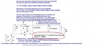
I found the mistake in your ASC.
You have tried to turn the probe off with .Set Prb=0
No such statement in Spice, you need to have .Param Prb=0
I should have noticed that immediately on your screen captures, but as usual when we are both on-line, it was late here.
Best wishes
David
Hi Damir
I found the mistake in your ASC.
You have tried to turn the probe off with .Set Prb=0
No such statement in Spice, you need to have .Param Prb=0
I should have noticed that immediately on your screen captures, but as usual when we are both on-line, it was late here.
Best wishes
David
Last edited:
Hi Damir
I found the mistake in your ASC.
You have used .Set Prb=0 to turn the probe off.
No such statement in Spice, you need to have .Param Prb=0
I should have noticed that immediately on your screen captures, but as usual when we are both on-line, it was late here.
Best wishes
David
Hi David,
You are right here, there is no dot command .set. Interesting thing is that LTspice does not show an error on it and in the example LoopGain2 this lead me to wrong dot command, look the attachment.
BR Damir
Attachments
Of course, that is sensible but this is DIY and I have broken amp with a 70V, regulated power supply so about 300W/8R for me. I'm hoping the higher rails and consequential part changes won't imbalance the layout which I believe is critical to the success of this design. Am I too far out of the sweet spot to get this to work stably with the boards you're making?
With 70V this amp can get 270W/8ohm but at 4 ohm output transistor power dissipation get critical. To get 300W/8 you need 75V and it can't drive 4 ohm with four pairs.
... LTspice does not show an error on it and in the example LoopGain2 this lead me to wrong dot command, look the attachment.
LTspice does show this as an error, look at the error log.
The text in LoopGain2 is only a comment, that you need to set the value of Prb to zero to turn off the probe, not the exact syntax for the command.
But it would be better to have the actual command.
It is too easy to just reproduce the comment text, almost automatically if you don't consciously think about it, even if you know the correct syntax.
Paul seems to have done the same, and I didn't notice immediately either. So it's not just your mistake.
So now you don't have to waste effort and remove the probe all the time.
Best wishes
David
Thanks, that's more than enough power as you have already stated. The loudspeakers I am likely to use this amp with average 6R so I'm not very concerned with the few visits it will take to 4R. How close to runaway am I with 4R and a 1.2K/W heatsink (assume ideal thermal contact)? I have some matched beefy Sanken bi-polars ready to go for this application.
Last edited:
LTspice does show this as an error, look at the error log.
The text in LoopGain2 is only a comment, that you need to set the value of Prb to zero to turn off the probe, not the exact syntax for the command.
But it would be better to have the actual command.
It is too easy to just reproduce the comment text, almost automatically if you don't consciously think about it, even if you know the correct syntax.
Paul seems to have done the same, and I didn't notice immediately either. So it's not just your mistake.
So now you don't have to waste effort and remove the probe all the time.
Best wishes
David
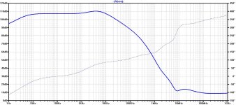
Thank you. Now, I am able yo measure PSRR without disconnect the probe.
Thank you. Now, I am able yo measure PSRR without disconnect the probe.
If there was not David persistence to solve the problem I will proceed to use it (I think Bimo you copied the mistake from me, sorry for that), LTspice did not stop and I took it as Thian probe quirk.
Thank you. Now, I am able yo measure PSRR without disconnect the probe.
It is a pleasure to help people who want truth.
")
One final comment is that I wrote that LTspice does show an error, but I should have added that the error description does not make very clear what the real problem is.
So I have learned too.
Best wishes
David
Damir, pretty nice PSRR.
If there was not David persistence to solve the problem I will proceed to use it (I think Bimo you copied the mistake from me, sorry for that), LTspice did not stop and I took it as Thian probe quirk.
It's OK, Dadod.
Without your help, may be I can take longer time to learn how to measure phase margin and gain margin.
Black Pearl
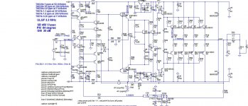
This one is with ThermalTrak output transistors. Technical specification is same or very close but with much better thermal behavior. OPS contains two TT BJT pairs and two ordinary BJT pairs.
I prefer to have the drivers on separate heat sink together with the bias spreader transistor.
Damir
This one is with ThermalTrak output transistors. Technical specification is same or very close but with much better thermal behavior. OPS contains two TT BJT pairs and two ordinary BJT pairs.
I prefer to have the drivers on separate heat sink together with the bias spreader transistor.
Damir
Attachments

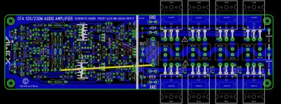
Second attempt to layout a decent PCB single side , dual layer it's to easy to do
Alex
Very nice Alex. I have to study it and probably I will come with some more suggestion. I never did this kind of layout myself, with the output transistors fixed directly to the main heat sink, so I need some time to analyze it and learn from it.
Damir
Second attempt to layout a decent PCB single side , dual layer it's to easy to do
Alex
Alex may I suggest some more changes (improvements?)
1. Make the PCB wider in the IPS part, let say the same as it is the distance between output transistor pairs tips. In this case you can make input stage closer to the OPS and then connection shorter.
2. I would like to have the drivers heat sink grounded, maybe to use kind of alu bracket with the foot wide about 1 cm and fixed to the board with screws from below and grounded in the same time. Other possibility is to use some extruded alu heat sink with enough low thermal resistance.
3. If possible make one bias transistors closer to the one of the output transistors. and the other one close and fixed to the drivers heat sink.
4. Put one faston connector between R0 and input connector, this should be then connected to the common start ground outside the board.
It is good that you removed the fuses from the PCB, they are not needed here. I would suggest a regulated power supply (something similar to the cap multiplier) I used in my TT amp, with all needed protection incorporated.
I hope that my suggestions are not annoying.
best regards
Damir
- Home
- Amplifiers
- Solid State
- Unique CFA 120/230W amp