Seems if the loop gain is increased then a CFA may be vulnerable to the same excessive sensitivity to component variation as a complementary VFA.
Now I think about it, maybe not, but it's very late here, will think more tomorrow.
Dave thank you for your help. The asc I attached was ready to test the square wave, hence the input shunt cap disconnected and the source is square wave. Change it to sin and connect the cap, but even without cap I don't see any instability problem. I am sure that you know that to test for the close loop gain the Tian probe should be removed. I don't see any indeterminate VAS current problems.
BR Damir
BR Damir


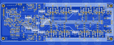
First try ,not ready it's a lot of work and time to short ..... have few hours to slip and go to work again ....

Regards Alex
Oh Alex you are so quick and I am so slow to communicate all needed data. Great work!
First some information about resistor wattage you need to know and I did not put it on the schematic.
1. The feedback resistors, important not to go in thermal distortion.
R37 (560R) should be 10W, maybe to use parallel array of lower wattage resistor.
R9 (22R) should be minimum 1W better 2W
2. R10, R30 should be minimum 1W better 2W.
3. Q6, Q8 dissipate 0.7W and could work without heat sink, but better keep it just in case.
And now one suggestion if you allow me.
It is quite important to have the feedback trace from the output to the feedback input as short as possible. I suggest you to flip 180 degree the OPS part and have the loudspeaker connection and the power connection in the middle of the PCB closer to the input part.
Thank you Alex very much.
P.S. My idea was to use separate small heat sink for the drivers (Q13, Q14 max 8W of dissipation) to remove them from main heat sink and bigger temperature fluctuation of the output transistors, and that is way I used two transistor bias spreader (Q23, Q24) and one of them to be fixed to the main heat sink other one to the drivers heat sink. Drivers work in A class and no large change in the power dissipation.
BR DAmir
Last edited:
The asc I attached was ready to test the square wave, hence the input shunt cap disconnected...
Disconnection of the input shunt not only removes the input filter but also alters the loop gain and response.
I know some people say to disconnect the input shunt, but then it is not the amplifier you will use and results won't be accurate, so I don't see the point
I am sure that you know that to test for the close loop gain the Tian probe should be removed.
I don't remove the Tian probe at all, I just turn it off with Prb (or whatever).
Why do you think it needs to be removed? Perhaps this is a mistranslation?
I don't see any indeterminate VAS current problems.
Neither do I, your amp looks fine, it was just an idea that I wanted to kick around.
Perhaps it was discussed in the CFA thread but there were so many unsubstantiated claims and tantrums that I only skimmed there.
There are different ways to load the input common emitter complementary pair, resistive load, different types of current mirrors etc.
Some probably have indeterminate VAS issues, which ones?
Can we produce equal gain without indeterminate VAS? How?
This relates to ideas about VAS versus TIS and where to put the current gain, Beta enhanced VAS versus cascodes and so on.
Were there any useful results on this topic, from the CFA thread, or elsewhere?
Best wishes
David
Hi David,
I am completely with you regardin input filter, but some people here on this forum want to see slew rate value without it (something as internal SR).
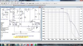
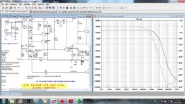
Attached plots show to different CLG, one with only prb turned off and next with prb turned off and Tian probe removed. It is obvious that Tian probe influences CLG simulation even with prb turned off.
I never simulated any CFA case (or I did not recognize) with indeterminate VAS issues. I tried different cases of resistive load and current mirrors (as a current conveyor). Mybe you can point the case where it could happened.
Best wishes
Damir
I am completely with you regardin input filter, but some people here on this forum want to see slew rate value without it (something as internal SR).
Attached plots show to different CLG, one with only prb turned off and next with prb turned off and Tian probe removed. It is obvious that Tian probe influences CLG simulation even with prb turned off.
I never simulated any CFA case (or I did not recognize) with indeterminate VAS issues. I tried different cases of resistive load and current mirrors (as a current conveyor). Mybe you can point the case where it could happened.
Best wishes
Damir
Attachments
...Attached plots show to different CLG, one with only prb turned off and next with prb turned off and Tian probe removed. It is obvious that Tian probe influences CLG simulation even with prb turned off
That definitely should not happen, there must be a mistake somewhere by someone.
It does not happen on my tests, I will look at my copy of your circuit to see if I can find out what this is about.
Best wishes
David
It seems that PRB is not actually turned off. Some times it's not obvious how LTspice picks up these values if there are multiple statements scattered around. Delete all the other text and see if it still happens.
I have just rechecked your circuit but with all the extra text removed. No difference with Tian probe removed or not. You seem to have a problem, please post both ASCs.
Last edited:
I think Prb is somehow set incorrectly.
Normally for a Tian it is set first to -1 then to 1.
When you have the "Step Param" statement commented there is only one run but the value of Prb is NOT set to 0, instead it seems to be -1 or 1.
Best wishes
David
Could you post the ASC of the problematic version?
Normally for a Tian it is set first to -1 then to 1.
When you have the "Step Param" statement commented there is only one run but the value of Prb is NOT set to 0, instead it seems to be -1 or 1.
Best wishes
David
Could you post the ASC of the problematic version?
Last edited:
I do not think Prb is turned off.
Normally for a Tian it is set first to -1 then to 1.
When you have the "Step Param" statement commented there is only one run but the value of Prb is NOT set to 0, instead it seems to be -1 or 1.
Best wishes
David
David, if you look post #47 first plot, there is .set prb =0 so it should be turned off, when step param is commented there is no run at all in my opinion. This is exactly how it is in LTspice LoopGain2 example.
BR Damir
p.s. You can try that with my asc file.
...there is .set prb =0 so it should be turned off..
Yes, it certainly should be turned off, but it seems that it is not.
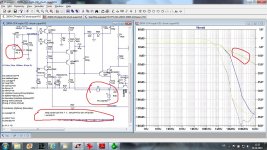
If you look at #47, the run where you Stepped Prb -1 and 1 with the input AC=1 then the red circled trace is the same as what you have in #49 when you have tried to set Prb off for the closed loop gain test. They just look different because the scales are different.
I learned back in the computer industry only to look at exactly the program that caused trouble.
Maybe an invisible control code or some other piece of hidden hexadecimal, who knows.
I wanted to save space on my small screen so I removed comments and the .Tran related text from the version you posted earlier and the problem does not occur there.
So could you post exactly the asc that shows this problem?
Best wishes
David
Last edited:
Attached plots show to different CLG, one with only prb turned off and next with prb turned off and Tian probe removed. It is obvious that Tian probe influences CLG simulation even with prb turned off.
Best wishes
Damir
Have noticed this exact behaviour myself on several simulations and completely removing probes solved it for me too.
Having .prb set to 0 did not have any effect.
Have noticed this exact behaviour myself on several simulations...
I have not seen this particular instance but I have certainly seen cases where LTspice apparently did not re-initialize some variables.
For instance a .Tran run would crash LTspice badly, not even an error screen, and repeatably.
But if I ran a .AC before the .Tran then no problem.
I think it is important to know why LTspice has messed up the value of Prb.
As if the Tian probe is not already important, what else may not work properly?
Best wishes
David
So while we wait for Damir to come back, did you read my earlier discussion points on VAS indeterminacy in CFAs?
Most CFAs work the IPS into the diode side of a current mirror whereas yours works into the collectors.
Did you wade thru the CFA thread and was this discussed?
Last edited:
I have not seen this particular instance but I have certainly seen cases where LTspice apparently did not re-initialize some variables.
For instance a .Tran run would crash LTspice badly, not even an error screen, and repeatably.
But if I ran a .AC before the .Tran then no problem.
I think it is important to know why LTspice has messed up the value of Prb.
As if the Tian probe is not already important, what else may not work properly?
Best wishes
David
Agreed. At least this "error" is easy to spot. Maybe a bit of research is in order.
So while we wait for Damir to come back, did you read my earlier discussion points on VAS indeterminacy in CFAs?
Most CFAs work the IPS into the diode side of a current mirror whereas yours works into the collectors.
Did you wade thru the CFA thread and was this discussed?
Yes, I saw your comments. Always though that using the current mirror would solve the VAS fighting issue as long as the front end doesn't suffer the same problem.
Some CFAs don't use a CMCL or the current mirror alternative so these could suffer from the symmetrical VAS fighting issue. This was discussed in the CFA thread along with the current mirrors being used for compensation as well.
Followed the CFA thread from the beginning so never needed to wade. However, have spent some time looking for specific bits of information. There is some good stuff buried away in there if you have the patience.
Paul
P.S. Will be reporting some findings soon, in your GFT thread, regarding alterntaive compensation schemes for my amp project.
Yes, it certainly should be turned off, but it seems that it is not.
If you look at #47, the run where you Stepped Prb -1 and 1 with the input AC=1 then the red circled trace is the same as what you have in #49 when you have tried to set Prb off for the closed loop gain test. They just look different because the scales are different.
I learned back in the computer industry only to look at exactly the program that caused trouble.
Maybe an invisible control code or some other piece of hidden hexadecimal, who knows.
I wanted to save space on my small screen so I removed comments and the .Tran related text from the version you posted earlier and the problem does not occur there.
So could you post exactly the asc that shows this problem?
Best wishes
David
Hi Devid,
This is asc file with that problem.
BR Damir
Attachments
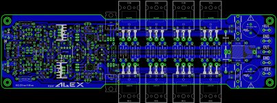
Good amplifier, dadod.
Hope many will build, when you get all things ready ....
Ditto and in the range of power-performance that I can use also.
Very interested if pcb can be developed.
THx-RNMarsh
I am glad to see Alex will try to make a PCB. dadod's idea deserve a shot.Ditto and in the range of power-performance that I can use also.
Very interested if pcb can be developed.
THx-RNMarsh
Power output can surely be modified. Via power supply voltage and adjustments.
What I am curious to see is WHAT Circuit of those posted
will be base for the PCB.
Maybe dadod can make up his mind and tell this to Alex.
- Home
- Amplifiers
- Solid State
- Unique CFA 120/230W amp