@pacificblue
"Even in class II equipment 0V must be connected to the chassis for safety reasons. If a wire of the audio supply comes lose and touches the case the corresponding fuse must blow to protect the equipment."
You've lost me there, I think. The chassis in Class II equipment is connected to audio 0V; understood. But not Earth, or Neutral. Correct?
"If a wire of the audio supply comes loose and touches the case" - does that means a mains wire? If it's a mains wire, the chassis becomes live, but the live fuse will not blow, because although the chassis is connected to 0V, it is isolated by a transformer from earth and neutral.
"...the corresponding fuse must blow to protect the equipment." Is this the mains Live fuse? How can it blow?
"If the case is not grounded, it acts like an antenna. If it is grounded, it acts like a shield."
This I understand, but it depends on your definition of "ground". What if the chassis is connected to Earth, but your circuitry and its 0V is isolated from Earth by a transformer, but enclosed in an earthed box? Does a genuine 'Earth' always act as a shield (e.g. a mobile phone in a subway), or must your circuitry's 0V have a relatively low impedance to the enclosure (and therefore earth) to obtain the shielding effect?
Hi,
connecting chassis to PE is for Safety ONLY. This PE to chassis connection is not needed for Audio reasons and Audio can manage perfectly well without it. In my view PE to Chassis reduces Audio quality.
Connecting exposed conductive parts to chassis is substantially for safety, but there is some interference attenuation available by doing this. However safety is the overriding criteria.
mixing a ClassI item in amongst a variety of ClassII items means that the Class becomes the PE connection for everything connected to the system.
A mains fault that makes a low voltage component live in any item will find it's way to earth and blow the fuse.
If you build a ClassI amp but leave the PE connection open or leave conductive parts not connected to a PE protected chassis, then a fault in any item of the equipment could leave an exposed part Live and no way for the Fault current to go to earth. The MCB and/or fuse does not break the RCCB does not detect imbalance in the Flow and Return currents.
The Fault and the Live parts justs sits there waiting for someone to touch it.
Is that explained any better?
Returning to my opening paragraph.
I said I believe that connecting Chassis to PE reduces Audio Quality.
My initial build of an amp or pre-amp is an open skeleton of modules, usually lying or secured to a strip of flooring. There is no shielding and no chassis as such. There is no connection to PE. all the exposed conductive parts are exposed. I rely totally on seeing that the transformer is isolating.
When ever I put this working prototype in a chassis and attach the PE I find without exception that audio quality deteriorates. I have never managed to make an encased amplifier nor pre-amp perform better when it was encased than when it was open to all forms of interference.
Last edited:
Hi Andrew
(You've been very patient with me, and I hope you don't mind my endless 'probing'. I'm just making the most of talking to someone who knows what they're talking about!)
"mixing a ClassI item in amongst a variety of ClassII items means that the Class [I?] becomes the PE connection for everything connected to the system. A mains fault that makes a low voltage component live in any item will find it's way to earth and blow the fuse."
The way I was thinking about it was that the Class I device *accidentally* becomes a sort of PE for the system, but not an 'official' PE, because otherwise the phono connectors and leads would have to be rated to suit whatever current the most powerful fuses ever encountered in Class II amplifiers are. They may, or may not be sufficiently short and stout to blow the fuse in the Class II device. They may or may not be inserted fully.
Are you implying that a Class II system is only 'safe' when there is a Class I item in there somewhere. What if there isn't? The faulty, live Class II components as described just sit there waiting for someone to touch them. Yes an RCCB, if fitted, wouldn't trip because of the fault, but it would trip as soon as a person touched the enclosure with sufficient sincerity to conduct the (non-fatal) trip current to earth. That's why I would fit an RCCB, not for it to trip automatically because of an internal electrical fault necessarily. I'm just slightly confused by what you think RCCBs are fitted for.
According to Wikipedia:
"A residual-current device (RCD), similar to a Residual Current Circuit Breaker (RCCB), is an electrical wiring device that disconnects a circuit whenever it detects that the electric current is not balanced between the energized conductor and the return neutral conductor. Such an imbalance is sometimes caused by current leakage through the body of a person who is grounded and accidentally touching the energized part of the circuit. A lethal shock can result from these conditions. RCDs are designed to disconnect quickly enough to mitigate the harm caused by such shocks although they are not intended to provide protection against overload or short-circuit conditions."
Sorry to keep going on about it!
It's funny you should mention the laying out of modules and finding that the performance suffers once you put them in an enclosure. I have just experienced *exactly* that scenario. The amplifier was the best hi fi I had ever heard with the modules laid out on the carpet, but when I put it in a box it became distinctly average, with or without a link between 0V and the earthed enclosure. I don't believe my own ears, though. I was expecting it to get worse - it couldn't have got any better - so I think my brain just gave me what I was expecting. I am convinced that psychology plays such a crucial role in this that non-blind listening tests are virtually meaningless. Can anyone convince me otherwise? (a subject for another thread, I think)
The chassis in Class II equipment is connected to audio 0V; understood. But not Earth, or Neutral. Correct?
Correct.
and"If a wire of the audio supply comes loose and touches the case" - does that means a mains wire?
"...the corresponding fuse must blow to protect the equipment." Is this the mains Live fuse? How can it blow?
Not a mains wire and fuse. If a wire comes loose that belongs to the audio circuit, i.e. on the secondary side of the transformer, the case must be connected to the 0V of the secondary side, so that the current has a low-ohmic return path and the fuse (that you have of course installed right after the transformer secondaries) blows. It is the same principle as class I for the mains, only restricted to the secondary voltage.
What if the chassis is connected to Earth, but your circuitry and its 0V is isolated from Earth by a transformer, but enclosed in an earthed box? Does a genuine 'Earth' always act as a shield (e.g. a mobile phone in a subway), or must your circuitry's 0V have a relatively low impedance to the enclosure (and therefore earth) to obtain the shielding effect?
A genuine Earth always improves shielding. The drawback is that a genuine Earth is not clean, because all kinds of devices (SMPS, filters, etc.) contaminate it. So it adds some interference of its own. That may be one of the reasons why you perceive the sound quality to go down when you put the amp into an enclosure. The other reason is that the components are closer to each other and capacitive and inductive coupling effects between them distort the signal.
Connecting your circuitry's 0V to Earth should in theory improve the sound. One reason is, it adds what is called virtual mass to the 0V. In analogy to the water model that is often used when describing electricity you can assume that the circuitry's 0V is a shallow lake, while the Earth is a deep one. We all know that still waters run deep. Now when you connect the two, the stilling effect of the deep lake (Earth) extends to the shallow one (circuitry's 0V) and your circuitry's 0V should be more stable when interference happens.
The second reason is that by connecting the two, your 0V reference includes the interference on the Earth. The signal so to say "floats" unaffected on the interference, like a boat that floats on water. The signal is comparable to the part of the boat that stays above the water and that remains more or less the same. When they are not connected it is more like a pole on the beach. Depending on the waves or the flood (both are interference) the part of the pole that remains above the water changes size.
Last edited:
@pacificblue
Many thanks for that very interesting information. For the shielding effect, is the impedance between your 0V and earth particularly critical? I saw in earlier parts of this thread that people were advocating parallel rectifiers and a resistor and/or capacitor to kill hum loops. Is this a method you would agree with?
Many thanks for that very interesting information. For the shielding effect, is the impedance between your 0V and earth particularly critical? I saw in earlier parts of this thread that people were advocating parallel rectifiers and a resistor and/or capacitor to kill hum loops. Is this a method you would agree with?
Ok, we are all in agreement that (for a class I device) the supply PE conductor must be connected to chassis so as to ensure that a line to case fault blows the fuse/trips the breaker/trips the RCD whatever measures are in place.
The 0V rail on the SECONDARY SIDE of the transformer is possibly a little more complex, in that there are several potentially reasonable things to do with it (And providing the transformer has an inter winding screen or is otherwise safe from primary/secondary shorts), there is no particular safety reason to favour one over the others (of course if the iron is designed such that there is ANY chance of a primary/secondary short then bonding the centre tap firmly to earth is the only thing to do).
You can bond it to chassis directly (and ideally at ONE point), this, provided that the external audio IO is not referenced to supply 0V, is good from a common mode perspective and is best practise for gear fitted with balanced IO. Cable screens should always be bonded directly to chassis at the point of entry (Helps to keep RF currents outside the case), but this is less then ideal where unbalanced interfaces are in play as if there is significant current flow in the cable screens it can impose an unfortunate noise voltage.
For single ended applications, you can connect all the IO connectors (typically phonos) screens together with a heavy bond wire and run a single connection from this to the electronics reference rail, which can then either be left floating (Ick, but you can) or bonded either directly of via a suitable impedance.
The key to all this is to keep circulating currents away from the audio signal reference.
One useful trick for single ended (and in very extreme cases, balanced circuits) is to include a very heavy bonding terminal externally for connecting a parallel Earth Conductor, this being a length of heavy wire run physically close to and in parallel with the cable screens. This conductor serves to lower the impedance seen between the connected equipment and thus the voltage developed by circulating currents.
See AES-48 for some interesting diagrams and also papers by Tony Waldron, Neil Muncy and Bill Whitlock for further reading.
Personally, in spite of the noise penalty (A simple '5532 differential input is ~14db noisier then a simple single ended input) I usually just make all the IO differential and ground the audio reference rail locally (it is never exported from the case).
Regards, Dan.
I saw in earlier parts of this thread that people were advocating parallel rectifiers and a resistor and/or capacitor to kill hum loops. Is this a method you would agree with?
There are two methods to deal with a hum loop.
a) Make the impedance between all grounds as low as possible so that the voltage difference that can develop is as low as possible.
b) Insert an impedance big enough to bring the equalisation currents between different ground potentials down.
Both methods intend to bring the ground loop hum down to inaudible levels. You describe method b).
(And providing the transformer has an inter winding screen or is otherwise safe from primary/secondary shorts), there is no particular safety reason to favour one over the others (of course if the iron is designed such that there is ANY chance of a primary/secondary short then bonding the centre tap firmly to earth is the only thing to do).
Many DIYers don't know how their transformers are designed. They are forced to assume the worst and should therefore always bond the centre tap to Earth.
Hey, your local thread necromancer reviving an old one from the dead, here.
Can someone please confirm to me that I got the basic concept of the proper star ground scheme. (for use without disconnect network). My case (temporarily is wood) So I just soldered a lug to the earth tab of the IEC connector wich is currently my main earth star. I assume to use the disconnect network, one has to place it between the star and the IEC tab.
Can someone please confirm to me that I got the basic concept of the proper star ground scheme. (for use without disconnect network). My case (temporarily is wood) So I just soldered a lug to the earth tab of the IEC connector wich is currently my main earth star. I assume to use the disconnect network, one has to place it between the star and the IEC tab.
Attachments
")
Dear all,
Sorry for haven't read through the Thread but can't wait to ask question !!!
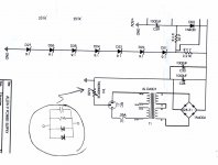
I found in some service manual, some manufactuer use a "CL-60" instead of the "Ground Break Circuit" (see attachment)
Will the CL-60 work 100% as "Ground Break Circuit" ?(Safty Protection, hum etc.,)
If the "L" touch the case by mistales, will my MCB (Main Circuit Breaker) jump up ?
Thanks in advance !!!!!!
Sorry for haven't read through the Thread but can't wait to ask question !!!
I found in some service manual, some manufactuer use a "CL-60" instead of the "Ground Break Circuit" (see attachment)
Will the CL-60 work 100% as "Ground Break Circuit" ?(Safty Protection, hum etc.,)
If the "L" touch the case by mistales, will my MCB (Main Circuit Breaker) jump up ?
Thanks in advance !!!!!!
Attachments
View attachment Visio-grounding plan - K4003.pdf
Hi all
I've read david davenport guideline and some of the posts but I find it difficult to identify the grounding problems without applying the principles to an example.
I hope I now use the different ground terms right.
Would anyone be so kind to have a look at my grounding plan and tell me if there is anything wrong or likely to cause hum?
cheers
Bastien
A good option for a clean earth is to use a medical grade IEC inlet connector by Schaffner or Schurter. These provide good mains filtration and with the medical specification also have a filtered earth. You can get the same in a non-medical version without the filtered earth if you so wish. Check out the relevant PDF's for the connector's to get the amount of filtration and at what frequency and current rating you need.
As to using your main earth tag on the inlet conjnector then I would choose to move it from there and to make that your star-point and take the inlet connector to that instead. It will provide cleaner paths for the earth too. There are many ways in which you can physically do this and all of which are very simple. A nut and bolt arrangement (fixed of course) with the necessary earths attatched via crimp connectors.
As to using your main earth tag on the inlet conjnector then I would choose to move it from there and to make that your star-point and take the inlet connector to that instead. It will provide cleaner paths for the earth too. There are many ways in which you can physically do this and all of which are very simple. A nut and bolt arrangement (fixed of course) with the necessary earths attatched via crimp connectors.
Thanks for the advice but I don't think I want to change the connectors but rather make sure the grounding is done to limit noise.A good option for a clean earth is to use a medical grade IEC inlet connector by Schaffner or Schurter. These provide good mains filtration and with the medical specification also have a filtered earth. You can get the same in a non-medical version without the filtered earth if you so wish. Check out the relevant PDF's for the connector's to get the amount of filtration and at what frequency and current rating you need.
I'm not sure I'm following youAs to using your main earth tag on the inlet conjnector then I would choose to move it from there and to make that your star-point and take the inlet connector to that instead.
Hello Bastien,
Look at the Velleman connection diagram here:
http://www.designnotes.com/downloads/K4003_Connection_Infosheet.pdf
I believe that they are suggesting that the input signal reference for each channel be connected to the system ground.
So:
1. Connect the mains safety ground directly to the chassis.
This may be the system star ground or it may be connected to another point which is the system star ground.
2. Isolate the input signal RCA jacks from the chassis.
3. Connect the shell of the Left input RCA jack to the system star ground.
4. Connect the shell of the Right input RCA jack to the system star ground.
5. Connect the Left signal input ground on the PC board to the system star ground.
6. Connect the Right signal input ground on the PC board to the system star ground.
7. The other "Ground" points on the PC board are not connected to the system star ground.
8. The power transformer is not connected to the system star ground.
Hopefully, Velleman tested this and it should provide humm-free operation.
Dave
Not sure this is strictly applicable as it primarily involved 600 ohm balanced circuits, but standard accepted practice in the broadcasting world is to have each piece of equipment use its own safety ground on its power plug. Then all interconnects to other locations the sheil of the beldfoil wire is only connected at one end, typically the source end. This couples signals with complete sheilding of wires from source to destination without creating any ground loops, which make themselves known real quick in high RF environments.
These practices were consistent between 2 radio and three television stations and three ground up sound studio constructions. They work.
Doc
These practices were consistent between 2 radio and three television stations and three ground up sound studio constructions. They work.
Doc
Dear all,
Sorry for haven't read through the Thread but can't wait to ask question !!!
I found in some service manual, some manufactuer use a "CL-60" instead of the "Ground Break Circuit" (see attachment)
Will the CL-60 work 100% as "Ground Break Circuit" ?(Safty Protection, hum etc.,)
If the "L" touch the case by mistales, will my MCB (Main Circuit Breaker) jump up ?
Thanks in advance !!!!!!
Anyone can help , please !
Thomas, post437.
Posts 431 to 436 each give some answers and Davenport gives almost all the answers.
Are you asleep?
Thank you so much !
I was waked Up with Excited !!!!!!!!

- Home
- Amplifiers
- Power Supplies
- understanding star grounding