rfbrw said:
No, it does not.
Sounds like we have different gossip sources?
")
Just because the datasheet says it's 23bit R2R ladder inside
so you belive it must be a classical R2R ladder? Hehe
finneybear said:
Sounds like we have different gossip sources?
Just because the datasheet says it's 23bit R2R ladder inside
so you belive it must be a classical R2R ladder? Hehe
I generally leave gossip to those to lazy to educate themselves. Referring to the TDA1541 as representative of the current state of the art in DACs makes as much sense as referring to the 80's Mazda RX-7 as representive of the current state of the art in car engines. The TDA1541 is neither representative or current but then you would know that if you bothered to educate yourself.
BTW if you are looking for a DAC that validates data on the falling edge of the clock, look no further than the TDA1541.
rfbrw said:
I generally leave gossip to those to lazy to educate themselves. Referring to the TDA1541 as representative of the current state of the art in DACs makes as much sense as referring to the 80's Mazda RX-7 as representive of the current state of the art in car engines. The TDA1541 is neither representative or current but then you would know that if you bothered to educate yourself.
BTW if you are looking for a DAC that validates data on the falling edge of the clock, look no further than the TDA1541.
Yes, those delta sigma, ring DAC breed like CS43122, PCM1792, etc
are so old and out of date such that using OSC inside does not
represent any advance in the state of art. Now, here I understand
your definition of so-call education!

finneybear said:
Yes, those delta sigma, ring DAC breed like CS43122, PCM1792, etc
are so old and out of date such that using OSC inside does not
represent any advance in the state of art. Now, here I understand
your definition of so-call education!
Putting aside from the fact that none of the dacs you referred to has an internal oscillator, this is about multibit R2R type dacs capable of fully static operation. The TDA1541 is not comparable to the PCM1704.
rfbrw said:
Putting aside from the fact that none of the dacs you referred to has an internal oscillator, this is about multibit R2R type dacs capable of fully static operation. The TDA1541 is not comparable to the PCM1704.
Well, check out PCM1792's datasheet for example, it clearly
states it has an auto clock frequency detection function inside.
You think what it is made of? You need something to synch
the data clock and the system clock, oK? Perhaps only
in your ancient land the definition of OSC is still made
of RC loops. Unfortunately, even the OSC in 1541 is not
like that!
As for the source of gossip, can we say it's coming from
deep inside BB? Let me stress this again, PCM1704 is
not your classical, static R2R ladder stuff.
As for TDA1541, it has two input mode, I2S and simultaneous
data loading mode. In the I2S mode, the data are
definitely latched at the rising edge. 99% of people are
using this I2S mode, so?
Anyway these are all irrelevant, XO is directly driving mostly
CD transport chips, chips around DAC chip,etc. All of these
are sych at the rising edge. Can you tell me any servo
chip which will synch on falling edges?
So my point still holds: Just measure where you will use. Hehe
Still feel your talk about education funny.
Perfect Square Wave
> so my suggestion is not to worry about the undershot too much. Usually it does no harm to the DAC performance.
Well I am not really worried, as I have not yet put any of those clocks in my CD player. But I thought I should mention my experience and make sure we all understand what we are looking at when oscilloscope outputs are posted on the forum.
Patrick
Re: Perfect Square Wave
Got it! Well, the rings are more interesting actually. Is it ring-free on your scope?
EUVL said:> so my suggestion is not to worry about the undershot too much. Usually it does no harm to the DAC performance.
Well I am not really worried, as I have not yet put any of those clocks in my CD player. But I thought I should mention my experience and make sure we all understand what we are looking at when oscilloscope outputs are posted on the forum.
Patrick
Got it! Well, the rings are more interesting actually. Is it ring-free on your scope?
Ringing
> Is it ring-free on your scope?
One overshoot to about 6V pk-pk, then a slight undershoot before settling to about 4.6V pk-pk (as I would expect). Some higher frequency noise after the undershoot, but I had not done a full noise analysis to make sure that it is not RF pick up from the environment. There was no reason to, as I was, as you pointed out, looking at stability of the rising (or falling) edges.
I'll post the results in 2 weeks when I get back to Germany. But I am sure any interested party would have done measurements and posted them by then. Or if no one would be interested, then no point for me to post either.
Patrick
finneybear said:
Hi Guido
Thanks for your points.
Unfortunately, PCM1704 has an osc inside, too. It also has
active current dividers inside. When you have to do a
23bit current divider, you do not have too many other choices.
"Short term deviation is not the only parameter that counts In judging jitter for audio clocks?"
Well, I have noticed that you keep posting overly-simplified,
blanket statements like this on this board again and again.
It's like a brainwash to many people here.
So can you tell me what "audio clock" is? Is there really
such a thing called "audio clock?" A clock is a clock.
The clock is used to drive the syncrhonous digital circuit
in DAC which is not much different from a clock driving
a communication gear running in 10GHz, synchronous mode.
The only difference is that the jitter performance requirement
for the clock used in CD applications is much less strigent than
the ones used in many communication equipments.
People in the communication industry even dare not make
blunt statement like yours, you know?
Now comes to the key point. Do all of the jitter elements
matter? The answer to me is a clear NO when you are
trying to make people to believe it's a Yes.
As I have mentioned above, it is only the timing of
the rising edge counts for a DAC, when you are considering the
XO only. The way you measure jittering based on both
rising and falling edges can actually give you a misleading
number, in turn, this may lead to a worsen result.
So this happens funny to me that when you keep saying
jitter matters, you are selling people a way to measure
the clock performance in an inadequate way.
Can you tell me why Allan deviation is not sufficient enough
to measure the timing performance at rising edges?
Or even modified Allan deviation does not cover enough
noise aspects?
I am not saying Tent XO is no good. On the contrary, it is
one of the best 50PPM XOs I have measured. (Note
the 50PPM here) Yet, please, do not make blanket statements
like those again. There's really not much complicated about XO for a DAC.
-finney
Fin
Could you explain why the PCM1704 has an osc ? Any idea on the PLL performance ? Any clue why BB engineers would put it in ?
Any clock could keep the spindle motor rotating, that is of no importance. The same clock, fed through many ICs, is used for conversion of data.
It seems you under estimate the importance of the clock when converting data. Again, a timing error is then translated into an amplitude error. It might be worth to realise how sensitive the ear is to (non harmonic !) amplitude distortion - once knowing that, we can translate that to jitter requirements.
In my perception, jitter contribution over 20kHz still audibly affects the results, though the ear is more sensitive to low frequency jitter content.
In my measurements I distinct between positive and negative slope, ofcourse, who says I mix the results ? Phase inversion between clock output and DAC input is daily practise in modern CD players, just to mention a single important aspect.....
I jumped into this discussion, because of the under / overshoot issue, and the way some measurements where taken.
Proper measurements may lead to the result I attached earlier. I am not stating that one HAS to apply a clock like that, but by surrounding it with a characteristic measurement environment, one obtains the results like that.
In my jitter measurements the clock output is loaded with 500 ohm.
You are free to ignore the cycle to 100k-cycle jitter importance. I hope others do not - they might learn from that and improve their digital playback.
I am not an expert on the Allen deviation measurement, but since it is a single number, it does not tell me ANYthing about the spectral content of the jitter. Ofcourse you may ignore that, but to me and many others it is of importance.
My clocks' output impedance is about 10 ohm. Could you explain to the community why that can be considered a current source ?
Attached is the jitter measurement result of one of my clocks
best regards,
Attachments
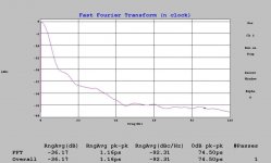
Well, since some us are interested in the jitter spectum.........
What sort of fancy gear made that plot?
And while we are at it, an excerpt from the PCM1792 data sheet:
I do not see anything that alludes to a PLL.
Jocko
What sort of fancy gear made that plot?
And while we are at it, an excerpt from the PCM1792 data sheet:
"The PCM1792 has a system clock detection circuit
that automatically senses if the system clock is operating between 128 fS and 768 fS..................(snip).............For optimal performance, it is important to use
a clock source with low phase jitter and noise."
I do not see anything that alludes to a PLL.
Jocko
Perfect Square Wave
Guido,
I am just a naive mechanical engineer so please forgive me for asking stupid questions. My only interest, as I am sure also many other's reading the forum, is to get the best out of these clocks, from yourself, Elso, LC or else.
In Post#14, you expressed your concern about undershoot potentially affecting timing. I understand it therefore that it is worth getting the XO to work under ideal conditions so as to avoid such.
In post#30, you mentioned that your measurements were made with a 500 ohm load at the XO output. Am I correct in interpreting that as, if the Tent XO, when in the actual circuit, is delivering less than 50mA (peak) pulsed current as can be measured via the 47 ohm series resistor, then we COULD add a load resistor between the clock input to the DAC and ground, after the cable, in order to make up the ballast so as to get the XO to operate without undershoot / overshoot ?
And in which case, should we not increase the supply voltage to 5.5V in order to restore the output voltage after the 47 ohm resistor to 5V ?
What would be the maximum continuous safe operating current for your XO ?
Thanks in advance,
Patrick
Hi Guido
I am surprised to see we would come to this discussion, too;
yet I feel technical talk like this is good and hopefully,
others will benefit from it.
Since my time is very limited tonight, let me talk about PCM1704 first.
In PCM1704, there are two 23bit DAC linked together in the co-linear mode
to make a full 24bit DAC. To make a full scale, static R2R 23bit DAC in
silicon is simply impossible. In fact, anything over 16 bit is out of
question. The most common solution is to put smaller DACs in parallel
to create a higher bit count DAC. As usual, ADI is more open about
describing their designs. In AD1865's datasheet:
http://www.analog.com/UploadedFiles/Data_Sheets/177648882AD1865_0.pdf
states that the 18bit DAC is actually made of fifteen! 14-bit R2R DACs.
Now imagine how many 14bit R2R DACs need to create a 23bit DAC?
It is 255 DACs! When you put 255 DAC together in parallel, you can not
just open them up all at the same time. Imagine suddenly you have
255 current sources driving the same output! So those smaller DACs
have to be arranged in a hierarchy fashion. Each node is controlled
by a MOS switch. Those switches will be turned on in stages. The stages
have to be arranged in a very precise timing sequence. Regular delay lines
simply can not make the cut, instead, a PLL, or more precisely, a DLL,
is used to control this timing sequence.
Here is another clue for you. Check out PCM1704's datasheet. It says
the output current swing is +-1.2mA. The output current settling time
from 0 to 1.2mA full step is 200ns. 1 second / (256 X 192KHz) = 20ns.
200ns / 20ns = 10 steps. Isn't this interesting?
As for the delta-sigma/multi-segment breed, the BCK, bit clock and SCK,
system clock are not necessarily coming from the same source.
This means BCK and SCK are not necessary in the same phase. So a PLL
is put in place to lock the clocks and to put everything in synch.
Otherwise the bit stream decimation process and delta sigma modulation
stage will be in trouble. The auto clock detection thing is just a nice
side benefit.
Be it a DLL or a PLL. The good news is that they are all deep inside
the chip. Any jitter generated by them will not cause any functional problem.
As far as the input data are latched correctly, you do not have to worry
about those internal jitters. The output result will be about the same anyway
It's those PLLs around the DAC chip which will be of real concern.
For instance, the PLL inside CS8414 to generate the system clock, SCK,
the PLL used to recover bit clock from the SPDIF line, etc.
-finney
Re: Well, since some us are interested in the jitter spectum.........
Hi Jocko
Wavecrest....
fancy indeed......
Jocko Homo said:What sort of fancy gear made that plot?
And while we are at it, an excerpt from the PCM1792 data sheet:
I do not see anything that alludes to a PLL.
Jocko
Hi Jocko
Wavecrest....
fancy indeed......
finneybear said:Hi Guido
I am surprised to see we would come to this discussion, too;
yet I feel technical talk like this is good and hopefully,
others will benefit from it.
Since my time is very limited tonight, let me talk about PCM1704 first.
In PCM1704, there are two 23bit DAC linked together in the co-linear mode
to make a full 24bit DAC. To make a full scale, static R2R 23bit DAC in
silicon is simply impossible. In fact, anything over 16 bit is out of
question. The most common solution is to put smaller DACs in parallel
to create a higher bit count DAC. As usual, ADI is more open about
describing their designs. In AD1865's datasheet:
http://www.analog.com/UploadedFiles/Data_Sheets/177648882AD1865_0.pdf
states that the 18bit DAC is actually made of fifteen! 14-bit R2R DACs.
Now imagine how many 14bit R2R DACs need to create a 23bit DAC?
It is 255 DACs! When you put 255 DAC together in parallel, you can not
just open them up all at the same time. Imagine suddenly you have
255 current sources driving the same output! So those smaller DACs
have to be arranged in a hierarchy fashion. Each node is controlled
by a MOS switch. Those switches will be turned on in stages. The stages
have to be arranged in a very precise timing sequence. Regular delay lines
simply can not make the cut, instead, a PLL, or more precisely, a DLL,
is used to control this timing sequence.
Here is another clue for you. Check out PCM1704's datasheet. It says
the output current swing is +-1.2mA. The output current settling time
from 0 to 1.2mA full step is 200ns. 1 second / (256 X 192KHz) = 20ns.
200ns / 20ns = 10 steps. Isn't this interesting?
As for the delta-sigma/multi-segment breed, the BCK, bit clock and SCK,
system clock are not necessarily coming from the same source.
This means BCK and SCK are not necessary in the same phase. So a PLL
is put in place to lock the clocks and to put everything in synch.
Otherwise the bit stream decimation process and delta sigma modulation
stage will be in trouble. The auto clock detection thing is just a nice
side benefit.
Be it a DLL or a PLL. The good news is that they are all deep inside
the chip. Any jitter generated by them will not cause any functional problem.
As far as the input data are latched correctly, you do not have to worry
about those internal jitters. The output result will be about the same anyway
It's those PLLs around the DAC chip which will be of real concern.
For instance, the PLL inside CS8414 to generate the system clock, SCK,
the PLL used to recover bit clock from the SPDIF line, etc.
-finney
Hi Fin
Thanks for feedback and insight in 1704 architecture - very interesting (TDA1541 also consists of more DACs - it grew from an industrial 11 bit / 200kHz DAC, first they applied 8 in the TDA1540)
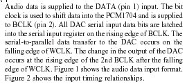
From what I read in the 1704 datasheet is that it converts on the BCK. I assume this is a straight wire from pin 2 right into silicon, not ?
Given the sonic results, I would be very much surprised if a PLL was inbetween.
The CS8412/14 PLL is not good enough for serious audio conversion. In addition, a secondary PLL could be added. I designed one and offer that as an add on module, see the TentLabs site.
cheers
Attachments
Re: Perfect Square Wave
Hi Patrick
Good observations
I suggest an RC network as termination. When applying that, the source does not have to fully energise the resistor, only at rf part of the pulse
If you want to experiment, add 47 ohm or so in series with the oscillator, close to the output. Take for example a small 500 ohm potentiometer (trimmer) in series with 10nF at the receiving end. Then tune the trimmer for flat response. Measure the value and replace by a fixed resistor (depending on the wiring you may end up with 50 to 150 ohm).
Now take a smaller cap like 100 pF and see if that is sufficient to dampen the overshoot. Experiment untill the smallest cap value does the job
Note: The above desribes load termination. Undershoot generated by the source, i.e. part of the output waveform, may not be suppressed (completely)
cheers
EUVL said:Guido,
I am just a naive mechanical engineer so please forgive me for asking stupid questions. My only interest, as I am sure also many other's reading the forum, is to get the best out of these clocks, from yourself, Elso, LC or else.
In Post#14, you expressed your concern about undershoot potentially affecting timing. I understand it therefore that it is worth getting the XO to work under ideal conditions so as to avoid such.
In post#30, you mentioned that your measurements were made with a 500 ohm load at the XO output. Am I correct in interpreting that as, if the Tent XO, when in the actual circuit, is delivering less than 50mA (peak) pulsed current as can be measured via the 47 ohm series resistor, then we COULD add a load resistor between the clock input to the DAC and ground, after the cable, in order to make up the ballast so as to get the XO to operate without undershoot / overshoot ?
And in which case, should we not increase the supply voltage to 5.5V in order to restore the output voltage after the 47 ohm resistor to 5V ?
What would be the maximum continuous safe operating current for your XO ?
Thanks in advance,
Patrick
Hi Patrick
Good observations
I suggest an RC network as termination. When applying that, the source does not have to fully energise the resistor, only at rf part of the pulse
If you want to experiment, add 47 ohm or so in series with the oscillator, close to the output. Take for example a small 500 ohm potentiometer (trimmer) in series with 10nF at the receiving end. Then tune the trimmer for flat response. Measure the value and replace by a fixed resistor (depending on the wiring you may end up with 50 to 150 ohm).
Now take a smaller cap like 100 pF and see if that is sufficient to dampen the overshoot. Experiment untill the smallest cap value does the job
Note: The above desribes load termination. Undershoot generated by the source, i.e. part of the output waveform, may not be suppressed (completely)
cheers
Re: RC Termination
Patrick,
Yes, all in operation when tuning (touching your trimmer may affect the whole, as will the osciloscope)
Once you know which wiring impedance you have, you can also derive the termination resistor = chrateristic impedance. Then the only thing left is the cap
Another challenge is not to terminate and to tune the series resistance at the source side only.....
cheers
EUVL said:Guido,
Good answers are always most appreciated.
Would you suggest trimming the RC network while connected to the DAC under operation? Surely the DAC presents some sort of load ?
And how about voltage level after the 47 ohm resistor ?
Patrick
Patrick,
Yes, all in operation when tuning (touching your trimmer may affect the whole, as will the osciloscope)
Once you know which wiring impedance you have, you can also derive the termination resistor = chrateristic impedance. Then the only thing left is the cap
Another challenge is not to terminate and to tune the series resistance at the source side only.....
cheers
Cable Impedance
> Once you know which wiring impedance you have
50 ohm Tefzel coax. Less than 10cm.
So assume 50ohm at the load end. Even with a cap to shift DC, would the ac current then not be something like 25mA ? I assume your XO can take 200mW without much problems ??
How about voltage amplitude then ?
Or would you suggest using 100 ohm coax instead ?
Got to go. Till later perhaps.
Patrick
Re: Cable Impedance
Hi Patrick
The trick is to reduce cap value as much as possible. Terminating is only required if the electrcal length is considered long. That means that using 50 ohm and a small cap will only affect the very high frequency part of the square wave, and all others will see higher impedance hence amplitude will not be affected
I myself am still happy with short twisted wiring
succes
EUVL said:> Once you know which wiring impedance you have
50 ohm Tefzel coax. Less than 10cm.
So assume 50ohm at the load end. Even with a cap to shift DC, would the ac current then not be something like 25mA ? I assume your XO can take 200mW without much problems ??
How about voltage amplitude then ?
Or would you suggest using 100 ohm coax instead ?
Got to go. Till later perhaps.
Patrick
Hi Patrick
The trick is to reduce cap value as much as possible. Terminating is only required if the electrcal length is considered long. That means that using 50 ohm and a small cap will only affect the very high frequency part of the square wave, and all others will see higher impedance hence amplitude will not be affected
I myself am still happy with short twisted wiring
succes
- Status
- This old topic is closed. If you want to reopen this topic, contact a moderator using the "Report Post" button.
- Home
- Source & Line
- Digital Source
- Undershoot in Kwak clock 7