I want to make unbalanced line ICs.
For this application ChatGPT recommended Mogami W2534 quad-core. Strangely (me thought) AI told me to employ only the braided shield for ground return and only the centermost conductor for signal. Is there potential advantage in using the 3 remaining unused conductors and if yes, how?
Please comment and/or suggest otherwise. The proposed RCA unbalanced line IC connects preamp output about 40-ohm > sub amp input about 12k-ohm. About 25' on the R side, about 3.5' on the L side (2 sub amps)
TX! Surprised no thread referral!

Do you leave the chassis of the receiving device floating?I use Mogami if it is handy. I use all the blues together as positive and clears as ground. I tie the shield to ground on one end only and label that end as source. It’s good cable.
I'm in my late 60s and have not made unbalanced braided shield line IC for decades. When I needed unbalanced I just used a twisted pair but I need the braided shield now for noise. Your recipe rings a bell; pretty sure that's exactly the recipe I used prior. Your recipe seems a lot better than AIs, no surprise that. TX.I use Mogami if it is handy. I use all the blues together as positive and clears as ground. I tie the shield to ground on one end only and label that end as source. It’s good cable.
Is Mogami star-quad easier to strip than Canare? Stripping Canare is a PITA.
Mogami is a lot easier to work with than Canare, and I think it sounds a bit better. Regarding the shield, leaving it disconnected at one end is what is known as a telescoping ground. The unconnected end should go to the destination device. Still use the clear or whichever color you use for the ground or negative conductor on both ends.
Mogami W2534 quad-core, is a good cable for XLR balance interconnect cables used in harsh electrical environments.
And while it will work just fine for a short RCA cable interconnect it's far from first choice. (it will be good for a long interconnect if wired correctly)
Best choice is a coax cable with a heavy braided shield.
Note: if you are set on using it for an RCA interconnect. attach 1 of the wire to the center pin and the other 3 wires and the shield to the shells at both ends.
I haven't made RCA ICs in years but also recall that the shield should only be connected to the negative connection at the source end.I use Mogami if it is handy. I use all the blues together as positive and clears as ground. I tie the shield to ground on one end only and label that end as source. It’s good cable.
See Figure 5 here: https://www.ranecommercial.com/kb_article.php?article=2127I haven't made RCA ICs in years but also recall that the shield should only be connected to the negative connection at the source end.
If you don't connect the load end, it doesn't have a clean signal reference ("ground") for the incoming audio signal.
The main reason is to reduce Common Impedance Coupling Noise currents (power line related noise currents). A low impedance path is required from shell to shell and this is best done with a heavy shield.speedskater, can you explain why the shielding needs to be connected at both ends? I didn’t connect it at all and it seems ok but I‘ve only just recently made mine and these are the first I’ve done.
Also a shield that is not connected at both ends will have poor high frequency interference rejection.
The problem of grounding in audio is that capacitive noise pickup, magnetic noise pickup and mains-safety all have different and somewhat mutually incompatible requirements on how grounds are wired. For audio the gold standard is shielded twisted pair differential signaling, because this decouples signal grounds in different pieces of equipment entirely and separates the shield to only provide capacitive screening and perhaps PE too.
Single ended audio cabling is always a compromise one way or another, though generally it can be made to work sometimes a bit of help is needed like ground-lifting circuits or extra ground drain wires. If you have shielded twin core you have the option of lifting signal ground from chassis ground at one end of the connection.
Single ended audio cabling is always a compromise one way or another, though generally it can be made to work sometimes a bit of help is needed like ground-lifting circuits or extra ground drain wires. If you have shielded twin core you have the option of lifting signal ground from chassis ground at one end of the connection.
Years ago I made RCA ICs using uopp solid silver wire and two conductor shielded cable. In all cases I used only one 24 or 26 AWG condutor at positive and one wire plus the shield at the source end. So, one last question regarding the Cat5e I'm using, it has 4 twisted pairs and I think I should only solder one solid colored wire to positive and one striped wire, from a different pair, and shield to negative. Does that make sense?
Thanks
Thanks
Last edited:
No, it doesn't make sense.one solid colored wire to positive and one striped wire, from a different pair, and shield to negative. Does that make sense?
Just use a coax with a braided shield.
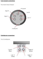
Most phono carts do not have one pin connected to the tone-arm. Otherwise the cart would be a dual "balanced" signal source. The input to the pre-amplifier with Cinch/RCA connectors is pseudo-balanced, i.e. the outer conductor is not tied to box at that point. Signal ground and case ground is joined somewhere inside the box.
The tonearm, which forms a shield for the internal four wires from the cart, is tied to the chassis of the turntable, and at some point bonded to one of the shields if an RCA cable. If not, a separate ground/chassis cable may be provided to bond against the pre-amplifier case.
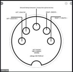
In a DIN turntable, 5 conductors are used, two for each channel and one for the shield. The shield does not carry any signal, nor should it. Typically the shield need only to be grounded at one end, usually at the pre-amplifier end.
This is to avoid ground loops. Removable head-shells have 5 pins.
The shield(s) may be connected to pin1 on a 3-pin XLR connector, or a 5-pin (or even 6-pin) XLR can be used like a 5-pin DIN.
Tying a signal conductor to a shield is not a good idea (signal currents should not be mixed with shield currents) but it should work in most cases.
Using shielded power cables should be standard. There are even double shielded power cables available form Gotham. Standard shielded AC wired can be ordered from Amazon for not much money.
"Ground" is a concept, not a wire.
https://www.clarkwire.com/pinouts/xlr-audio-pinouts
https://en.wikipedia.org/wiki/DIN_connector
The tonearm, which forms a shield for the internal four wires from the cart, is tied to the chassis of the turntable, and at some point bonded to one of the shields if an RCA cable. If not, a separate ground/chassis cable may be provided to bond against the pre-amplifier case.
In a DIN turntable, 5 conductors are used, two for each channel and one for the shield. The shield does not carry any signal, nor should it. Typically the shield need only to be grounded at one end, usually at the pre-amplifier end.
This is to avoid ground loops. Removable head-shells have 5 pins.
The shield(s) may be connected to pin1 on a 3-pin XLR connector, or a 5-pin (or even 6-pin) XLR can be used like a 5-pin DIN.
Tying a signal conductor to a shield is not a good idea (signal currents should not be mixed with shield currents) but it should work in most cases.
Using shielded power cables should be standard. There are even double shielded power cables available form Gotham. Standard shielded AC wired can be ordered from Amazon for not much money.
"Ground" is a concept, not a wire.
https://www.clarkwire.com/pinouts/xlr-audio-pinouts
https://en.wikipedia.org/wiki/DIN_connector
Attachments
What a lot of confusion in this thread already. Is this for phono or something else?
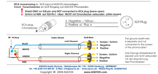
Star-quad cable, which maybe what Chat GPT suggested, is designed to cancel out magnetic fields more effectively that standard twisted pair. The geometry also gives it lower inductance. Please see pic below:

The idea with star quad is that the diagonally opposing conductors are tied together at both ends. So you end up with two signal lines (two sets of diagonally opposed pairs, normally color coded to help make clear which wires form pairs). They can be used as balanced interconnects, or with one pair as hot and the other pair as signal ground. If there is a shield it should be tied to chassis ground at the source end only.
Star-quad cable, which maybe what Chat GPT suggested, is designed to cancel out magnetic fields more effectively that standard twisted pair. The geometry also gives it lower inductance. Please see pic below:
The idea with star quad is that the diagonally opposing conductors are tied together at both ends. So you end up with two signal lines (two sets of diagonally opposed pairs, normally color coded to help make clear which wires form pairs). They can be used as balanced interconnects, or with one pair as hot and the other pair as signal ground. If there is a shield it should be tied to chassis ground at the source end only.
- Home
- Design & Build
- Construction Tips
- Unbalanced line: your braided/shielded wire and schematic?