if you go to Generg's house, the Muse controller might be the last thing you want to walk off with
...hehehe i know...
Your friends are my friends when I give them one Muse controller.....
sneaky !
...I think i'd rather relieve you of your BJ2 ...hehehehe.joking aside: I think I'll have a fantastic preamp with it....to compare to my trusty UGS.
Last edited:
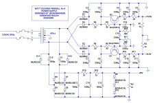
Here are a few SIT power supplies in addition to those already posted in this thread.
I have ordered a custom smps to play with. The amp sounded great with them at BA, so I am interested to try it out at home.
I have ordered a custom smps to play with. The amp sounded great with them at BA, so I am interested to try it out at home.
Attachments
The circuit requires not only a quiet supply, but one whose DC value is
regulated in some way.
My thoughts so far are for two Salas SSLV BiB PSUs. With a trimmer in the reference to allow for fine tuning of the bias
I am perplexed. Juma did not go to this or any extent in the design of his power supply he showed in the thread "VFET PP amp..".My thoughts so far are for two Salas SSLV BiB PSUs. With a trimmer in the reference to allow for fine tuning of the bias
I am perplexed. Juma did not go to this or any extent in the design of his power supply he showed in the thread "VFET PP amp..".
There's a bit of difference there - in my amp higher rails are not intended just for biasing the VFETs, they supply the power for the input stage and the EF that drives the VFET and I implemented the way to bias the VFETs precisely (by pots that change the current through the input stage) so there is no need to have regulated power supply because if the Vgs rail sags, the Vds rail will sag too, and the output VFETs (having a triode output characteristics) will keep the same Id.
In Mr. Pass' circuit biasing voltage sources are just that - there is only a negligible amount of current through them (the Ig of VFETs) so the Vgs/Id dependency is being served directly from voltage sources and that's why they have to be regulated/adjustable. Of course, the Vds power supply voltage has to be stiff in that case.
the Vds power supply voltage has to be stiff in that case.
The Ids of the SITs has a strong dependency on the Vds, enough that a
relatively small variation in DC on the rails gives a large bias change. If you
do not regulate the supply, then you should be prepared to adjust the bias
automatically.
The Ids of the SITs has a strong dependency on the Vds, enough that a
relatively small variation in DC on the rails gives a large bias change. If you
do not regulate the supply, then you should be prepared to adjust the bias
automatically.
How small variation is small enough? Would a regulated supply with a vanilla 3-pin LM-regulator in series be good enough or is it something you'd want to improve further?
Pretend that the device is an 8 ohm resistor. 4 volt rail change gives
0.5 Amp bias change. This is not exact, but it gives you a feel for it.
It's important that the rails be clean of AC noise, but also that variations
for DC are kept within limits. For Class A operation, if you have a 3 pin
regulator that can handle three times the bias current and decouple it with
a simple RC circuit, like 0.47 to 1 ohm and a few thousand uF to ground, you
should be in good shape.
the Vds power supply voltage has to be stiff in that case.
The Ids of the SITs has a strong dependency on the Vds, enough that a
relatively small variation in DC on the rails gives a large bias change. If you
do not regulate the supply, then you should be prepared to adjust the bias
automatically.
That's exactly what I wrote - using the word stiff in meaning "of constant value; not changing". Where do we differ ?


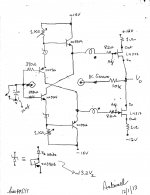
Potential bias circuit for PP SIT amp
Zen Mod. The attached schematic shows a potential method to bias the PP SIT. Its prototype works satisfactorily. Its purpose was to demonstrate and maybe extend the feasibility to PP SIT. The components of this demonstrator circuit are:
Zen Mod. The attached schematic shows a potential method to bias the PP SIT. Its prototype works satisfactorily. Its purpose was to demonstrate and maybe extend the feasibility to PP SIT. The components of this demonstrator circuit are:
- A dual +/-15 V regulated power supply for the bias circuit.
- A dual +/-12 V regulated power supply fpr the output stage.
- LM337 [negative voltage regulator] was used to simulate a P-channel depletion device. LM317 [positive voltage regulator] was used as an N channel depletion device. Both devices loosely simulate complementary power SITs. Their Adjust port is like a gate. Their Input port is like the drain, and their Output port is like the source.
- The front end is a complementary BJT voltage level shifter.
- The interstage BJTs are complementary buffers which apply the bias voltage to the Adjust terminal of the chips via the secondary transformer windings which also carry the audio signal.
- The variable pots [1K Ohm] are used to adjust bias current which is monitored [closely] across the 1 Ohm source power resistor.
- The prototype has a dc servo function. A resistor [e.g. 10 K Ohm] is connected from the Vo output port to the joint bases of the front end BJTs which are AC grounded with an electrolytic cap . The DC voltage accumulated on this cap is processed to automatically center the dc voltage at Vo to ~ zero volts.
- Close the shorting switch [to ground] across the electrolytic cap to disable the servo function.
- Turn on the +/-15 V supply only to energize the bias circuit.
- Adjust the bias voltage at the emitter ports of the interstage buffers to +/-14 V referenced to ground. The +/-2 V difference between the bias at the Adjust port and the respective +/- 12 V power rails inhibits the conduction of the chips.
- Short Vo to ground.
- Work with one chip at a time. For example, decrease the initial bias voltage [+14 V] slowly while monitoring the resultant voltage drop across the source resistor of LM337. I settled at 200 mA because of limited heat sink capability.
- Ditto to the lower chip to get ~200 mA.
- Lift the power outport from ground. DC offset maybe present and small.
- Engage dc servo by opening the grounding switch across the front end electrolytic cap.
- Check the voltage at the electrolytic cap to coincide with its polarity. Reverse the leads of the cap if needed.
Attachments
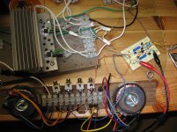
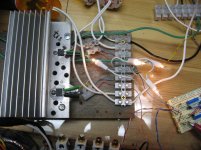
Zen Mod. Pictures of the transient prototype are attached for the schematic I showed in the previous post. Not pretty; but is fortunately a knowledge plant. The protoboard has the bias regulator, and the chips are on the heat sink. The left toroid [120V to dual 12 V] delivers the audio signal and is driven by the headphone amp of a CD player.
Attachments
- Status
- This old topic is closed. If you want to reopen this topic, contact a moderator using the "Report Post" button.
- Home
- Amplifiers
- Pass Labs
- Ultrasimple SIT PP amp from BAF , or SIT Beast with a Thousand PSUs