Interesting thread. Just to let others see something of the schematics and pcb layout more easily, here are screenshots of them. For the original pdf file, see early part of thread.
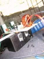
Note that the output inductor is NOT shown either on the schematic or the pcb layout - whether air or ferrite cored it probably deserves to be tied down somehow.


Note that the output inductor is NOT shown either on the schematic or the pcb layout - whether air or ferrite cored it probably deserves to be tied down somehow.
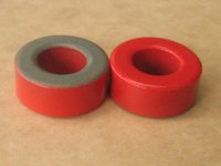
is it T106-2 iron powder? Seems like yellow T106-26 to me...
It is Red with Brown color on the other side, the yellowish glow must've been the cam flash effect

Attachments
ohh.. nice, those bds run little hot at +/- 50vdc but they still survive. IRF540N and IRF9540N is a good combination. nice setup. u need good power supply they will suck big current from it.
thanks Norazmi, will take note of that
Member
Joined 2009
Paid Member
I've just been looking into Class D amps and found this thread. It is titled 'Ultra simple class D'. Excuse my ignorance, but I thought class D amps hd a digital part too them, high speed triangle wave generator, comparators etc. This doesn't have any of these, so how is it a class D.
Actually ClassD means only 1 thing: the power stage switches fully on and off. No dedicated generators and comparators, etc. is needed, however you can find everything in this circuit if you want:
- the whole thing is an oscillator, the triangle signal is the ripple current of the inductor, and the feedback signal also contains an approximate triangle
- comparator is not else than an overdriven amplifier. Here it is built from 2 stages.
"Digital?" Not. The signal is represented not by voltage, but by duty cycle which is continuously variable, so it is not digital, but analog. Like frequency modulation.
...Like frequency modulation.
Or even, to be exact about it, Pulse Width Modulation, PWM.
I suppose you could say that the output having only two states, before it goes through the low pass filter, means it's "sort of digital" - but not in the usual sense. The 'D' being the initial of digital is coincidence, afaik.
Ok. Thanks guys.
So, has anyone built this circuit and if so, how does it sound? I have built a few chip amps, LM3875 and LM3886 and they sound stunning. My recent cMoy amp has transformed my headphones, so I was wondering if I could expect any where near the same quality from this, or would I need to build a more complicated class D?
Please can someone explain the principle of this amp. I've had a search on Google for triangle wave generators, and see that this can be achieved with an oscillating opamp feeding into another, but I can't understand how the circuit here works. I understand that U1C is a obviously just a buffer, and am I right in thinking U1B is being used as a Shmitt trigger, to turn the MOSFETS on and off? So that just leaves U1A and U1D.....Are these being used to make the triangle waveform with the original output from U1C superimposed on it?
Thanks again for any help
Last edited:
OK. I just found a free piece of software written in Java that allows you to build and simulate circuits. It seems to be very good so far. Here is a screenshot of the 'simple class d' amp:
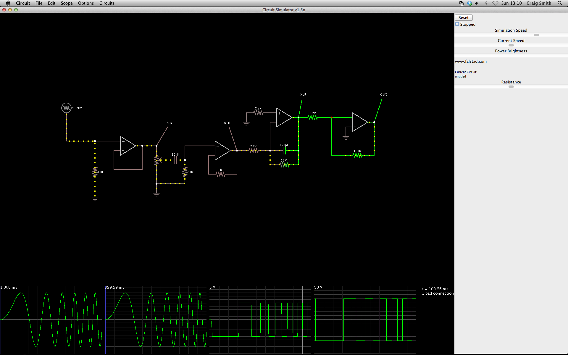
I put a sweeping ac signal at the front of the circuit and you can see the output square wave responding to it (the right hand side scope).
I am running it on my Mac, but as it is Java, it should run on any operating system.
You can get a copy of the java application from here:
Circuit Simulator Applet
Cheers. But still, how does the circuit actually work?
http://www.diyaudio.com/forums/class-d/210387-hi-can-anyone-help-me-circuit.html
Don't try to simulate separately! The whole circuit is an oscillator, it doesn't work without the global feedback.
Last edited:
- Home
- Amplifiers
- Class D
- Ultra Simple Class D